Introduction
The document provides an overview of sensor integration to SRSDK software. For choosing appropriate sensor settings, understanding of Image Proc and Image Sense path is necessary.
Figure 1‑1 depicts the high-level block diagram of Sabre CSI controllers connected to Image Proc / Image Sense path. The top block depicts different blocks within Image Proc, second block depicts CSI host controller feeding Image Sense pipeline. The capabilities of Image proc / Image Sense block play a key role in choosing the sensor.
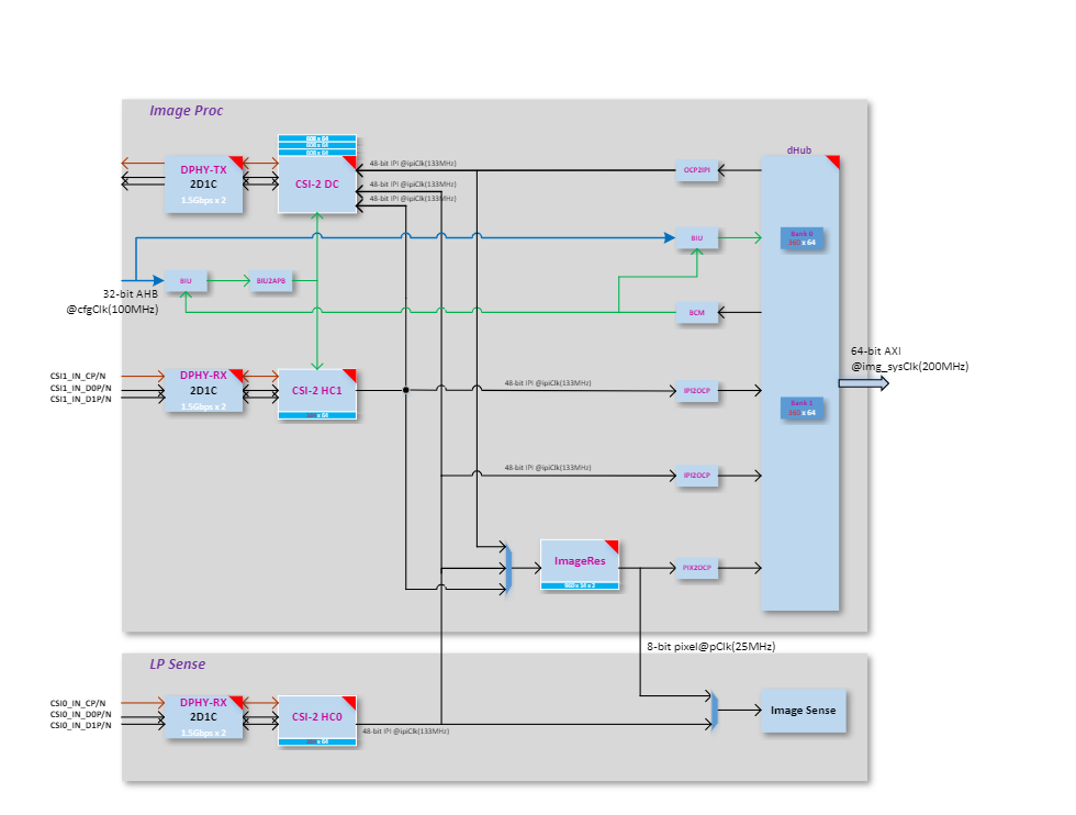
Figure ‑ ImageProc-high level block diagram
Sabre Capability
CSI Host controller
Max number of lanes per CSI host = 2
Max data lane rate = 1500 Mbps per lane
Pixel bit depth = 8 or 10 bits.
Raw bayer / Monochrome/ RGB / YUV.
ImageProc
Operating clock = 133 MHz
LP Sense
Operating clock = 25 MHz
Sensor Clock
Sabre Clock Out = 24 or 19.2 MHz
Note: Other clock configuration possible and depends on Sabre PLL configuration.
Sensor Capability
To port the camera sensor, the following parameters must be checked and compared against CSI & LP Sense capability:
MIPI Clock Mode: continuous or non-continuous mode.
Num of lanes.
Pixel Depth.
Frame Rate.
Frame width and Height (include blanks).
Or
Width and Height (without blanks).
Sensor Clock frequency.
MIPI clock rate.
Table ‑ MIPI Clock Calculation
PixelRate = FrameWidth * FrameHeight * fps MIPI Bandwidth = PixelRate * Bits_per_pixel Datarate per lane = MIPI Bandwidth/number_of_lanes MIPIClkRate (differential) = Datarate_per_lane/2 |
|---|
Sensor Settings provided by Vendor: FrameWidth=2560 FrameHeight=2250 FrameRate = 30 PixelDepth = 10 PixelRate = 172.80000 MipiClkRate = 432.00000 Datarate per lane = 172.8*10/2 = 864Mhz |
Sensor Integration
Settings Selection
Based on the comparison below, pick up the appropriate settings from sensor vendor.
Compare Sensor’s MIPI Lane clock, lane, and bit depth capability against Sabre CSI host controller capability.
Check Sensor input clock’s requirement.
Sensor’s pixel rate must be lower than LP Sense clock (25Mhz) when CSI Host controller connected to LP sense path
Sensor’s MIPI Clock (MIPI Clock *2) must be less than or equal to 1500 Mbps per lane when CSI host controller connected to Image Proc path.
Sensor Addition
Follow the below steps to add a new sensor to SRSDK.
- Add sensor register settings folder to
common/components/ext_drivers/img_sesnors
Sensor registers folder contains source and include folder.
- In source folder, add sensor register file with different sensor
resolution / MIPI clock-based settings array provided by sensor vendor.
- In include folder, expose sensor specific array or function
prototype.
Enter Sensor index.
- Add sensor index (one for passthrough and another for sensing) to
sensors_types_e enumeration in common/components/ext_drivers/img_sesnors/common/include/img_Sensor_common.h
- Add sensor related array and functions to “entry_table_setting”
array.
3. In “sr100_ext_drivers.clayer.yml”, add new sensor files for compilation.
Sample Application
Sample Application (imgproc_demo_rx.c) supports pass-through and sensing with two different sensor configurations. Two different settings allow the user to perform the different operations.
Sensing with low resolution.
Pass through with higher resolution.
Sensing after downscaling.
Sensing while passthrough with low resolution.
Sensing after scale while passthrough with high resolution
Configuration
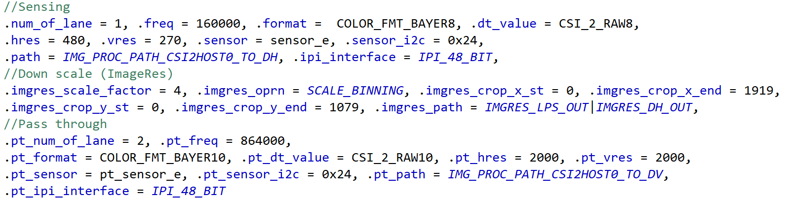
Add new config structure to sensor-based configuration array in sample application. Below structure configures Image Prop pipeline with Sensor parameters and Image Res parameters that depends on sensor frame size.
Select Sensor in “SENSOR_TYPE” Macro.
Edit HRES_MAX and VRES_MAX as per the width and height chosen for sensing. These 2 fields control the size of the frame being dumped to memory. Since Image Proc pipe writes frame width (HRES_MAX) as multiple of 24, align width but don’t edit other width in the configuration array.
typedef struct _img_config {
// Sensing Parameters
int num_of_lane; // Num of lanes
int freq; // MIPI Data rate per lane
int format. // Rx pixel depth
int dt_value; // Tx pixel depth
int hres; // Width (without blanks)
int vres; // Height (without blanks)
int sensor; // Sensor Index
int sensor_i2c; // Sensor I2C address
int path; // choose from image_proc_data_path_t
int ipi_interface; // 48- or 16-bit IPI interface
// ImageRes (Downscale) Parameters
int imgres_scale_factor; // Sub-Sampling or Binning factor
int imgres_oprn; // Sub-Sampling or Binning
int imgres_crop_x_st; // Crop Start X
int imgres_crop_x_end; // Crop End X
int imgres_crop_y_st; // Crop Start Y
int imgres_crop_y_end; // Crop End Y
int imgres_path; // Output to ImageProc/LP Sense path/both
// Pass through Parameters
int pt_num_of_lane;
int pt_freq;
int pt_format;
int pt_dt_value;
int pt_hres;
int pt_vres;
int pt_sensor;
int pt_sensor_i2c;
int pt_path;
int pt_ipi_interface;
}img_config;
typedef enum image_proc_data_paths{
IMG_PROC_PATH_CSI2HOST0_TO_DV = 0, // CSI Host-0 to CSI Tx in pass through mode
IMG_PROC_PATH_CSI2HOST0_TO_DH, // CSI Host-0 to memory in sensing mode
IMG_PROC_PATH_CSI2HOST0_TO_DH_DV, // CSI Host-0 to CSI Tx and memory
IMG_PROC_PATH_CSI2HOST1_TO_DV, // CSI Host-1 to CSI Tx in pass through mode
IMG_PROC_PATH_CSI2HOST1_TO_DH, // CSI Host-1 to memory in sensing mode.
IMG_PROC_PATH_CSI2HOST1_TO_DH_DV, // CSI Host-1 to CSI Tx and memory.
IMG_PROC_PATH_DHUB_TO_DV, // CSI Host-0 to CSI Tx and memory.
IMG_PROC_PATH_CSI2HOST0_TO_IMGRES, // CSI Host-0 to memory after down scale.
IMG_PROC_PATH_CSI2HOST1_TO_IMGRES, // CSI Host-1 to memory after down scale.
IMG_PROC_PATH_CSI2HOST0_TO_IMGRES_DV,//CSI Host-0 to memory after down scale and Tx(no scale)
IMG_PROC_PATH_CSI2HOST1_TO_IMGRES_DV, // CSI Host-1 to memory after down scale and Tx (no scale).
IMG_PROC_PATH_INVALID_LAST,
}image_proc_data_path_t;
Table ‑ Image Proc Configuration Example
SW Flow
Sensor Streaming Start
When the sensor operates in continuous clock mode, it sends a stop state signal only once i.e. before starts streaming. In such a case, MIPI data path must be started before sensor streaming because MIPI DPHY relies on stop state signal to trigger the internal calibration.
When the sensor operates in non-continuous clock mode, it sends a stop state signal at the end of frame data packets. In such case, MIPI data path can be started after or before sensor streaming.
Sample functions.
For verification of different use cases listed below, refer to imgproc_demo_rx.c
Sensing:
Capture Frame to System memory: vTaskMipiRxCamera
Capture Frame to memory after LP sense processing: vTaskImgProcToSense
Pass through: vTaskMipiPassThrough
vTaskMipiDataPathChange
Switching between Sensing and pass through
Sensing while pass through with / without Image Res (downscale) in path. Here incoming frame written to memory after downscaling while transmitting the same frame (without downscaling) to CSI Tx.
.
Copyright
Copyright © <<year or year span>> Synaptics Incorporated. All Rights Reserved.
Trademarks
Synaptics; the Synaptics logo; are trademarks or registered trademarks of Synaptics Incorporated in the United States and/or other countries. All other trademarks are the property of their respective owners.
Notice
This document contains information that is proprietary to Synaptics Incorporated (“Synaptics”). The holder of this document shall treat all information contained herein as confidential, shall use the information only for its intended purpose, and shall not duplicate, disclose, or disseminate any of this information in any manner unless Synaptics has otherwise provided express, written permission.
Use of the materials may require a license of intellectual property from a third party or from Synaptics. This document conveys no express or implied licenses to any intellectual property rights belonging to Synaptics or any other party. Synaptics may, from time to time and at its sole option, update the information contained in this document without notice.
INFORMATION CONTAINED IN THIS DOCUMENT IS PROVIDED “AS-IS,” AND SYNAPTICS HEREBY DISCLAIMS ALL EXPRESS OR IMPLIED WARRANTIES, INCLUDING BUT NOT LIMITED TO ANY IMPLIED WARRANTIES OF MERCHANTABILITY AND FITNESS FOR A PARTICULAR PURPOSE, AND ANY WARRANTIES OF NON-INFRINGEMENT OF ANY INTELLECTUAL PROPERTY RIGHTS. IN NO EVENT SHALL SYNAPTICS BE LIABLE FOR ANY DIRECT, INDIRECT, INCIDENTAL, SPECIAL, PUNITIVE, OR CONSEQUENTIAL DAMAGES ARISING OUT OF OR IN CONNECTION WITH THE USE OF THE INFORMATION CONTAINED IN THIS DOCUMENT, HOWEVER CAUSED AND BASED ON ANY THEORY OF LIABILITY, WHETHER IN AN ACTION OF CONTRACT, NEGLIGENCE OR OTHER TORTIOUS ACTION, AND EVEN IF SYNAPTICS WAS ADVISED OF THE POSSIBILITY OF SUCH DAMAGE. IF A TRIBUNAL OF COMPETENT JURISDICTION DOES NOT PERMIT THE DISCLAIMER OF DIRECT DAMAGES OR ANY OTHER DAMAGES, SYNAPTICS’ TOTAL CUMULATIVE LIABILITY TO ANY PARTY SHALL NOT EXCEED ONE HUNDRED U.S. DOLLARS.
Ordering Information
For ordering information and a complete list of Synaptics’ products, contact your Synaptics sales representative. Visit our website at www.synaptics.com to locate the Synaptics office nearest you.
Contact Us
Visit our website at www.synaptics.com to locate the Synaptics office nearest you.