1.0 Installation
Use SynaTool Kit from Release package: <SRSDK>/tools/
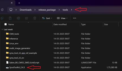
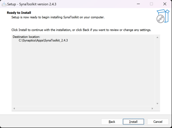
Run SynaToolkit installer and follow the instructions:
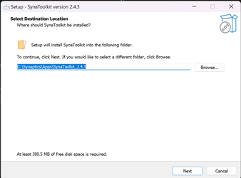
The default installation folder for SynaToolkit is: C:SynapticsAppsSynaToolkit_2.4.3
2.0 Menu Bar
2.1 Main
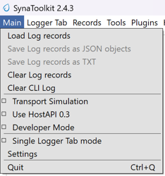
2.1.1 Load Log Records
Purpose: Users can load previously saved log files for analysis or review.
Steps:
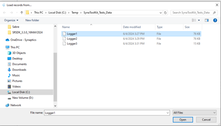
Navigate to Load Option: In the main menu, locate and click the Load log records option to initiate the file selection process.
Select Log File: The available log files such as Logger1, Logger2, and Logger3 will be listed with details like modification date and file size. The correct file format to load and view the logs in the Logger Tab is “.log“.
Open Log File: Click on the desired log file to select it. The file name will appear in the ‘File name’ field at the bottom of the window. Click the Open button to load the file.
Result:
Upon successful loading, the data from the selected log file will be displayed on a new tab named after the log file (e.g., Logger1 tab for Logger1 file).
Troubleshooting:
If the log file does not load correctly, ensure the file format is supported, and check for permissions issues or file corruption. If problems persist, contact support.
2.1.2 Save Log Records
Purpose: Allows users to save the current state of log records from the active tab to a file on their computer.
Steps:
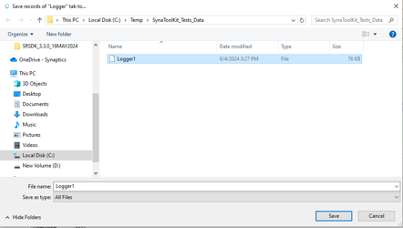
Initiate Save Process: Click on the Save Log records as JSON objects (or) Save Log records as TXT option located within the active log tab. This action will open a file saving dialog window.
Choose Save Location:
The dialog will display the most recently used directory, but you can navigate to other directories if you wish to save the log file elsewhere.
You can also create a new folder within the dialog if necessary by clicking on the New folder button.
Name the File:
Enter a name for your log file in the ‘File name’ field and append “.log“ to the name. If you’re overwriting an existing file, you can select it from the list in the dialog.
Save the File:
Click the Save button to save the log file. Ensure the file extension and name are correct before saving.
Note: Make sure that the log file is saved in a location where you have write permissions, to avoid any issues with file creation.
2.1.3 Clear Log Records
Purpose: Allows users to clear all current log records displayed in the application.
Steps:
Navigate to the specific tab where log records are displayed.
Select the option to clear logs. This will remove all data from the tab, ensuring it is empty for new data
2.1.4 Clear CLI Log
Purpose: Provides the functionality to clear the Command Line Interface (CLI) log, removing all command histories and outputs.
Steps:
Access the CLI interface within the application.
Execute the command or select the option to clear the CLI log. This action will erase all entries from the CLI log view.
2.1.5 Developer Mode
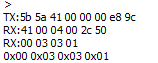
Purpose: Tailored for developers, this mode provides enhanced data outputs, such as RX/TX data, for debugging and development.
Mode Activation:
Enable Developer Mode from the application settings.
Expect additional data outputs (e.g., TX:5b 41 00 00 e8 9c) which are essential for in-depth analysis and troubleshooting.
2.1.6 Single Logger Tab Mode
Purpose: Streamlines operations by performing all actions related to log files—such as saving, loading, and clearing—within a single tab, without creating new tabs.
Mode Usage:
When this mode is enabled, select any ‘Save’, ‘Load’, or ‘Clear’ operation related to log files.
All actions are confined to the same tab, preventing the creation of additional tabs and simplifying the user interface.
2.1.7 Settings
a) Appearance Settings
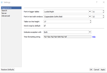
Purpose: Customize the visual elements of the application, including fonts, table row height, and other display features.
Steps:
Navigate to Settings and select the Appearance tab.
Modify the settings as needed:
Font in Logger Tables: Choose a font and size.
Font in Text Edit Windows: Select preferred font and size.
Table Row Line Height: Adjust to desired thickness.
Word Wrap: Enable or disable word wrap.
Time Formatting: Set the format for time display.
Apply changes by clicking Apply.
To revert to original settings, click Restore Defaults.
To cancel changes, click Cancel.
b) Search Settings
Purpose: Configure default search options to enhance finding specific logs or entries.
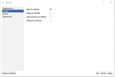
Steps:
Under Settings, go to the Search tab.
Set default behaviors for:
Open by Default: Automatically expand search results.
Regex by Default: Enable regular expression in searches.
Case Sensitive: Make searches sensitive to case.
Wildcard by Default: Allow wildcard characters in searches.
Save the settings with Apply, revert with Restore Defaults, or cancel with Cancel.
c) Server Settings
To be supported in future release.
d) Advanced Settings
Purpose: Fine-tune advanced operational parameters like logging level.
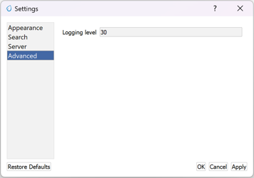
Steps:
Access Settings and navigate to the Advanced tab.
Adjust the advanced settings:
Logging Level: Set the verbosity of console output.
Use Apply to save, Restore Defaults to revert, or Cancel to exit without saving.
2.1.8 Quit
Close the GUI application
2.2 Logger Tabs
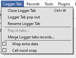
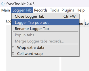
2.2.1 Close Logger Tab
Purpose: This command allows users to close the currently opened Logger Tab within the application.
Steps:
Navigate to the Logger Tab: Identify the Logger Tab you intend to close.
Close the Tab: Use the close option available on the tab, typically represented by an “X” or option from the menu.
Important Note: Ensure that all necessary data within the Logger Tab is saved prior to closing, as closing the tab may result in the loss of unsaved data.
2.2.2 Logger Tab Pop Out
Purpose: Enhances multitasking by allowing users to detach the Logger Tab from the main application window and operate it as an independent dialog window. This can be useful for comparing logs side-by-side or on different monitors.
Steps:
Locate the Logger Tab you wish to detach.
Click on an option “Pop Out”.
The Logger Tab will then open in a new window, separate from the main application interface.
Functionality:
The detached Logger Tab retains all functionality and can be interacted with as if it were docked in the main application window.
Adjust the window size and position as needed to suit your viewing preferences.
Note: To reintegrate the Logger Tab back into the main application window, use “Pop In“.
2.2.3 Pop In Tabs
Purpose: This operation allows users to reintegrate detached Logger Tabs back into the main application window.
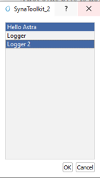
Steps:
Locate the Detached Tab: Find the Logger Tab window that has been popped out.
Reintegrate Tab: Use the “Pop In” option, usually available through a right-click context menu or a dedicated button in the tab’s title bar.
Confirm Integration: The tab should now appear back in the main application window, merged with other existing tabs.
Note: This feature is particularly useful for users who utilize multiple monitors or need to manage workspace efficiently by consolidating tabs.
2.2.4 Rename Logger Tab
Purpose: This function allows users to rename an existing Logger Tab to better reflect its content or purpose.
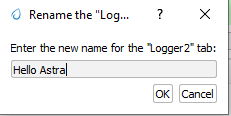
Steps:
Initiate Rename: Right-click on the Logger Tab you wish to rename and select the “Rename” option, or double-click the tab name if applicable.
Enter New Name: In the dialog box that appears, type the new name for the tab.
Apply Changes: Click OK to apply the new name.
Cancel Changes: If you decide not to rename the tab, click Cancel to leave the tab name unchanged.
Note: After renaming, ensure that the new name accurately reflects the tab’s content to avoid confusion.
2.2.5 Cell Word Wrap
Purpose: This feature ensures that text in a cell is wrapped to fit within the column width, improving readability and keeping the interface tidy.
Steps:
Access Logger Table: Navigate to the logger table where messages and other details are displayed.
Adjust Column Width: If the text in a cell exceeds the column width, the text will automatically wrap to the next line within the same cell.
Manual Adjustment: You can also manually adjust the width of the columns by dragging the edges of the column header if more or less wrapping is desired.
Note: Enabling word wrap helps in viewing longer messages without the need to horizontally scroll through the table, making it easier to read and analyze log data.
2.3 Records
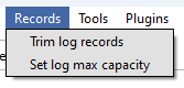
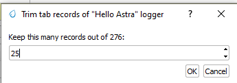
2.3.1 Trim Log Records
Purpose: This feature allows users to trim the log to maintain only the most recent entries, which can help in managing space and improving log readability.
Steps:
Initiate Trim: Open the log tab you want to trim and select the option to trim log records. This may be available in a menu or as a button.
Set Trim Criteria: A dialog box will appear asking how many of the most recent records you wish to keep. Enter the desired number.
Confirm: Click OK to apply the trim. The log will then only display the specified number of the most recent entries.
Cancel: If you change your mind, click Cancel to exit without trimming the log.
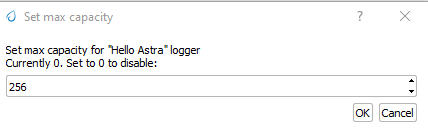
2.3.2 Set Log max capacity
Purpose: This function allows setting a maximum capacity for log records. When the set number is exceeded, older entries will be automatically deleted to make room for new ones.
Steps:
Access Capacity Settings: From the log management settings, select the option to set the maximum log capacity.
Specify Capacity: In the dialog box, specify the maximum number of log entries to retain. Enter 0 to disable this limit.
Apply Changes: Click OK to save the setting. The log will automatically manage its entries to not exceed this number.
Cancel: Click Cancel if you decide not to set or change the capacity.
Note: Setting a maximum capacity can help in maintaining performance by limiting the number of log entries stored at any one time. Ensure you choose a limit that balances performance with the need for historical data.
2.4 Tools
2.4.1 Script Editor
Purpose: The Script Editor facilitates the creation, editing, and management of scripts composed of supported commands for testing or operational purposes.
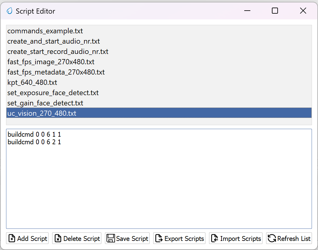
Features:
Create and Edit Scripts: Develop new scripts or modify existing ones using supported commands from the command menu and custom commands like sleep.
Save and Manage Scripts: Save modifications, delete scripts no longer needed, and refresh the script list to reflect recent changes.
Import and Export: Transfer scripts between different systems or environments for consistency and backup.
Execute Scripts: Run scripts directly against the hardware or software environment to automate tasks and test scenarios.
Steps:
Access the Script Editor:
Navigate to the Script Editor from the main application menu or toolbar.
Creating or Modifying Scripts:
Click Add Script to start a new script or select an existing script from the list to edit it in the script text area below.
Enter or modify the command sequence according to your testing needs.
Saving and Managing Scripts:
Click Save Script to preserve any new changes.
To delete a script, select it and click Delete Script.
Use Refresh List to update the script display after adding, editing, or deleting scripts.
Importing and Exporting Scripts:
Use Import Scripts to load scripts from an external file.
Click Export Scripts to save the selected script externally for use on other systems or for backup.
Executing Scripts:

To run a script, select it from the list and click Execute Script. Ensure you are connected to the appropriate hardware or software environment where the script will run.
Monitor the execution process and results directly within the application.
Note: Before executing scripts, especially those that modify settings or operational parameters, ensure they are thoroughly tested to avoid unintended consequences
2.4.2 Registers Info Data Base
To be supported in future release.
2.4.3 Memory Analyzer
To be supported in future release.
2.4.4 Video Streamer
The Video Streamer in Synatoolkit is used to stream the video output of the usecase being executed. There are various options that can be configured in the video streamer.
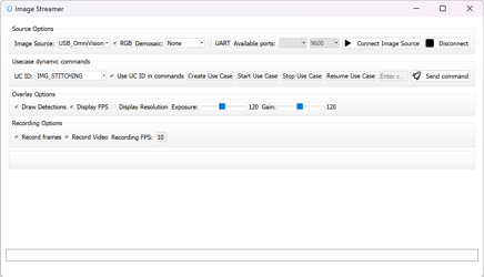
Source Options: Facilitates the selection of Image Source, and Demosaic, option to Connect Image Source, and Disconnect from Image Source.
Usecase Dynamic Commands: Facilitates the selection of UC ID, Buttons to Create Use Case, Start Use Case, Stop Use Case, Resume Use Case, Send Command, and field to enter the build command.
Overlay Options: Facilitates selection of displaying the Detections, Resolution and FPS, also control of Exposure and Gain.
Recording Options: Facilitates the recording of Frames, Video and FPS.
2.4.5 Pin Configurator
To be supported in future release.
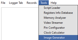
2.4.6 Image Generator
Prerequisite:
Add “Arm GNU Toolchain arm-none-eabi13.2 Rel1bin” to path.
These are steps for creating a B0 image and burning the flash using the SynaToolKit GUI.
2.4.6.1 Creating the image
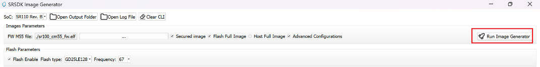
By clicking the “…“ in the FW 55 file option, browse the .elf/.axf file to be converted to .bin.
Untick the “Host Full Image“ option. Make sure the “Secured Image“, “Flash Full Image“, and “Flash Enable“ options are checked. Choose the Flash type for your hardware
Check the “Advanced Configurations“ option.
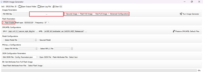
Under “Model Configurations“, check the “Select Model File”. By clicking the “…“, browse the .bin file. For eg: the .bin file in SRSDK can be found in commonapplicationssample_applicationsinferenceinference_basic_flash_sample_app. Refer ../SRSDK_How_to_compile_a_new_model_into_project.pdf to convert tflite model to .bin using vela compiler.
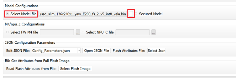
Click on “Run Image Generator“.
The Model.bin file will be created in <path to Synatoolkit>binOutputB0_FlashComponents.
The Flash binary will created in <path to Synatoolkit>binOutputB0_Flash.
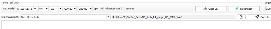
2.4.6.2 Flashing the image
Ensure that the SR110 is properly connected to the system per the SR110 User Guide. ..docsAstra_SR_MCU_Quick_Start_Guide.pdf provides instructions on how to setup the SR110 to flash firmware.
Under SynaTool CMD, select “FW“ and the COM port corresponding USB connector on the SR110 from the dropdown.
Click on “Connect”.

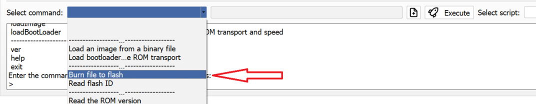
In the “Select Command” dropdown, click on “Burn file to flash“.
Follow the below steps to run inference from model burned in flash.
Select the Model.bin generated in the <path to Synatoolkit>binOutputB0_FlashComponents.
Once the file is selected, click on the filename and append the address 0x629000 as shown below.

Click on “Execute”.
d. Wait till the flashing is complete. Connect the SR110 to the system via UART1 using the UART-USB dongle to obtain the logs.
Repeat steps 1 to 5 to update firmware image. Click on “+“ icon and select the .bin file generated in <path to Synatoolkit>binOutputB0_Flash and click on “Execute“. Wait till the flashing is complete.

Reset the platform
2.4.6.3 Command line based Image generation and flashing
The following describes the instructions for creating a B0 .bin file using the image generator command line tool, instructions are also included on how to burn the image to flash.
2.4.6.3.1 Creating Image
Location: |
<path to Sy natoolkit>srsdk_image_generator while using python script <path to Synatoolkit>bin> while using executable |
|---|---|
Python Script: |
srsdk_image_generator.py |
Windows Executable: |
srsdk_image_generator.exe |
Input: |
Required Parameters: -spk external_componentSPKArchi veRC3.0ASICSecureDevelopemen tspk_rc3_0_secure_otpk_0605.bin -apbl toolssrsdk_image_generatorB 0_Input_examplessr100_b0_bootlo ader_ver_0x0134_ASIC_Release.axf -m55_image sr100_cm55_fw.axf (Arm Compiler Output) or sr100_cm55_fw.elf (GCC Output) One of Parameters below must be provided: -flash_image for Flash Images -host_image for Host Images Optional Parameters: -model (model bin file) -flash_type MX/GD/WB (default is MX) -flash_freq 34/67/100/134 (default is 67) -Q4 (default 1, support Q4) -json_attr <xyz>.json (See Configuration JSON files for list of possible inputs) -B0 (default is B0) -sdk_secured/-sdk_non_secured (Specify SDK secured/non secured) -model_secured/-model_non_secured (Specify Model secured/non secured) -v (The SRSDK Image Generator Version) Configuration JSON files: flash_attributes.json - flash attributes parameters config_Parameters.json - General addresses and memory regions definitions images_Parameters.json - Image Parameters definitions for Secured and non-secured functionality NVM_data.json - NVM Data fw_Update_Parameters.json - Data for FW Update (Multi Image Data) |
Outputs: |
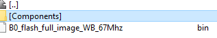
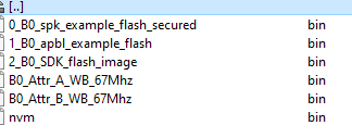
In Output folder there are two Folders: “Flash” and “Host” In “Flash” folder there is file with full image. The folder ‘Components’ contains all the sub images that are combined to make the full image.
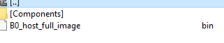
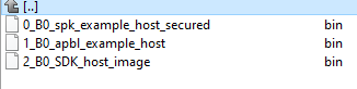
In “Host” folder there is file with full image. The folder ‘Components’ contains all the sub images that are combined to make the full image.
|
Dependencies: |
For .axf, the ARM Compiler is required and for .elf GCC Toolchain is required. Below given are the environment variables and their corresponding values to be set: For .axf:
AC6_TOOLCHAIN_6_19_0 -
C:Program
FilesArmDevelopment Studio
2022.2swARMCompiler6.19bin
For .elf:
GCC_TOOLCHAIN_13_2_1 -
C:Program Files (x86)Arm GNU
Toolchain arm-none-eabi13.2
Rel1bin
In case for run srsdk_image_generator.py need to install python packages by command: pip install -r requirements.txt |
Below instructions are alternative to Syna Tool GUI for Image Generation |
|
Execution example for non secure flash binary |
Using Executable: .srsdk_image_generator.exe -B0 -flash_image -sdk_non_secured -spk “C:sabreexternal_componentSP KArchiveRC3.0ASICNonSecures pk_rc3_0_nosecure_romk_0605.bin” -apbl “.B0 _Input_examplessr100_b0_bootloa der_ver_0x0134_ASIC_Release.axf” -m55_image “.B0_Inp ut_examplescm55_fw_example.axf” -flash_type GD25LE128 -flash_freq 67 Using Python: Can be used from power shell or Linux python .srsdk_image_generator.py -B0 -flash_image -sdk_non_secured -spk “C:sabreexternal_componentSP KArchiveRC3.0ASICNonSecures pk_rc3_0_nosecure_romk_0605.bin” -apbl “.B0 _Input_examplessr100_b0_bootloa der_ver_0x0134_ASIC_Release.axf” -m55_image C:sabreoutsr100_cm55_fwsr100_b0 _fw_hwReleasesr100_cm55_fw.axf -flash_type GD25LE128 -flash_freq 67 |
Execution example for secure flash binary |
Using Executable: .srsdk_image_generator.exe -all_images -B0 -flash_image -sdk_secured -spk “C:sab reexternal_componentSPKArchiv eRC3.0ASICSecureDevelopement spk_rc3_0_secure_otpk_0605.bin” -apbl “.B0 _Input_examplessr100_b0_bootloa der_ver_0x0134_ASIC_Release.axf” -m55_image “.B0_Inp ut_examplescm55_fw_example.axf” -flash_type GD25LE128 -flash_freq 67 Using Python: Can be used from power shell or Linux python .srsdk_image_generator.py -B0 -flash_image -sdk_secured -spk “C:sab reexternal_componentSPKArchiv eRC3.0ASICSecureDevelopement spk_rc3_0_secure_otpk_0605.bin” -apbl “.B0 _Input_examplessr100_b0_bootloa der_ver_0x0134_ASIC_Release.axf” -m55_image C:sabreoutsr100_cm55_fwsr100_b0 _fw_hwReleasesr100_cm55_fw.axf -flash_type GD25LE128 -flash_freq 67 |
Execution example for non secure host binary |
Using Executable: .srsdk_image_generator.exe -B0 -host_image -sdk_non_secured -spk “C:sabreexternal_componentSP KArchiveRC3.0ASICNonSecures pk_rc3_0_nosecure_romk_0605.bin” -apbl “.B0 _Input_examplessr100_b0_bootloa der_ver_0x0134_ASIC_Release.axf” -m55_image “.B0_Inp ut_examplescm55_fw_example.axf” Using Python: Can be used from power shell or Linux python .srsdk_image_generator.py -B0 -host_image -sdk_non_secured -spk “C:sabreexternal_componentSP KArchiveRC3.0ASICNonSecures pk_rc3_0_nosecure_romk_0605.bin” -apbl “.B0 _Input_examplessr100_b0_bootloa der_ver_0x0134_ASIC_Release.axf” -m55_image C:s abreoutsr100_cm55_fwsr100_b0_ fw_hwReleasesr100_cm55_fw.axf” |
Execution example for secure host binary |
Using Executable: .srsdk_image_generator.exe -B0 -host_image -sdk_secured -spk “C:sab reexternal_componentSPKArchiv eRC3.0ASICSecureDevelopement spk_rc3_0_secure_otpk_0605.bin” -apbl “.B0 _Input_examplessr100_b0_bootloa der_ver_0x0134_ASIC_Release.axf” -m55_image “.B0_Inp ut_examplescm55_fw_example.axf” -B0 -host_image -sdk_secured -spk “C:sab reexternal_componentSPKArchiv eRC3.0ASICSecureDevelopement spk_rc3_0_secure_otpk_0605.bin” -apbl “.B0 _Input_examplessr100_b0_bootloa der_ver_0x0134_ASIC_Release.axf” -m55_image C:sabreoutsr100_cm55_fwsr100_b0 _fw_hwReleasesr100_cm55_fw.axf |
Execution example for for model binary generation |
Using Executable: .srsdk_image_generator.exe -all_images -B0 -flash_image -sdk_secured -spk “C:sab reexternal_componentSPKArchiv eRC3.0ASICSecureDevelopement spk_rc3_0_secure_otpk_0605.bin” -apbl “.B0 _Input_examplessr100_b0_bootloa der_ver_0x0134_ASIC_Release.axf” -m55_image “.B0_Inp ut_examplescm55_fw_example.axf” -flash_type GD25LE128 -flash_freq 67 -model_non_secured -model “<PATH><model_vela>.bin” Note: Choose the model binary generated using Vela compiler following “SRS DK_How_to_compile_new_model.pdf” Using Python: Can be used from power shell or Linux python .srsdk_image_generator.py -B0 -flash_image -sdk_secured -spk “C:sab reexternal_componentSPKArchiv eRC3.0ASICSecureDevelopement spk_rc3_0_secure_otpk_0605.bin” -apbl “.B0 _Input_examplessr100_b0_bootloa der_ver_0x0134_ASIC_Release.axf” -m55_image C:sabreoutsr100_cm55_fwsr100_b0 _fw_hwReleasesr100_cm55_fw.axf -flash_type GD25LE128 -flash_freq 67 -model_non_secured -model “<PATH><model_vela>.bin” |
2.4.6.3.2 Flashing Image
Location |
<path to Synatoolkit>\ |
|---|---|
Python Script |
synatool.py |
Execution Example for flashing the image |
python.exe synatool.py –fw –uart –comport <COMPORT> –baudrate 230400 –hostapi04 –b0protocol or python .synatool.py –fw –uart –comport <COMPORT> –baudrate 230400 –hostapi04 –b0protocol
|
Execution Example for flashing the model binary |
Flash model binary after flashing the image. python.exe synatool.py –fw –uart –comport <COMPORT> –baudrate 230400 –hostapi04 –b0protocol or python .synatool.py –fw –uart –comport <COMPORT> –baudrate 230400 –hostapi04 –b0protocol
|
2.5 Plugins
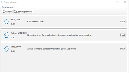
2.5.1 Plugin Manager
Purpose: The Plugin Manager in SynaToolKit allows users to install, manage, and update various plugins that enhance the functionality of the main software.
Features:
Install Plugins: Easily add new capabilities to the toolkit by installing plugins.
Access Installation Directory: View where plugins are stored on your system.
Refresh Plugin List: Update the list of available and installed plugins to reflect any changes or new additions.
Steps:
Opening the Plugin Manager:
Navigate to the Plugin Manager from the main menu or toolbar of SynaToolKit.
Installing a Plugin:
Browse the list of available plugins.
Click the Install button next to the plugin you wish to install. A progress indicator may appear to show the installation status.
Viewing Installed Plugins:
To view the installation directory and manage installed plugins, click Open Plugins Folder. This will open the folder in your system’s file explorer.
Updating Plugin List:
If you have added plugins manually to the directory or wish to refresh the list after an installation, click the Refresh button. This ensures that the Plugin Manager displays the most current information.
Note: Be sure to review the functionality and requirements of each plugin before installation to ensure compatibility with your current setup. Regular updates and management through the Plugin Manager will help maintain optimal performance and security of the software.
2.6 Help
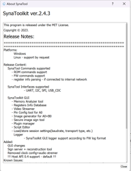
2.6.1 About SynaToolkit
Purpose: This section provides users with comprehensive information about SynaToolkit, including its version, features, and supported platforms.
Accessing Information:
Open About SynaToolkit: Navigate to the Help menu and select About SynaToolkit. This will open a window displaying detailed information about the toolkit.
Content Includes:
Version Number: Displays the current version of SynaToolkit, ensuring users know which version they are using.
License Information: Details the licensing under which SynaToolkit is released, including any user obligations or rights. This version is released under the MIT License.
Release Notes: Provides a summary of new features, improvements, and bug fixes in the latest release. Highlights from the latest notes include:
Support for various command types such as ROM, and FW commands.
Enhancements in GUI features like the Memory Analyzer and Video Streamer.
Introduction of new tools such as the Plugin Manager and Image Generator for B0.
Improvements and additions in connectivity options and simulation modes.
Platform Support:
SynaToolkit is primarily supported on Windows.
Guide to Release Notes:
Release Content: Details the commands and interfaces supported by SynaToolkit, along with new functionalities added in the update.
Added Features: Lists new tools and features introduced in the current version to enhance user interaction and toolkit performance.
Using this Information:
Use the About section to verify that your version of SynaToolkit is up to date and to understand the capabilities and limitations of your software. This is also useful for troubleshooting and when seeking support.
Note: Regular updates to SynaToolkit introduce new features and improvements. Keeping abreast of this information ensures optimal use of the toolkit.
3.0 Logger Functionality
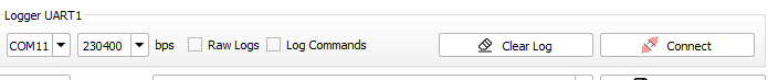
3.1 Logger Connect/Disconnect
Purpose: Facilitates the connection and disconnection of the Logger tool to and from UART1 Com ports, allowing for dynamic logging of system communications.
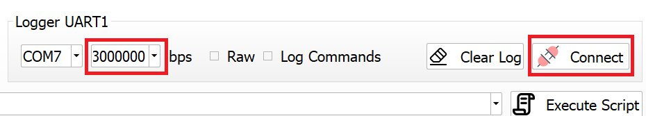
3.1.1 Connect
To Connect: Select the appropriate UART1 Com port and baud rate, then click the Connect button. A new Logger tab will open for each connection, displaying incoming log data.
Requirements: Ensure the correct COM port and baud rate are selected to establish a successful connection.
3.1.2 Disconnect
To Disconnect: Press the Disconnect button to terminate the connection with the logger.
Tab Persistence: The Logger tab will remain open and accessible even after disconnection, allowing you to review the logged data.

3.1.3 Clear Log
Functionality: Clears all data from the log buffer to free up space or prepare for new data.
Usage: Click the Clear Log button to remove all existing entries from the log display.
3.1.4 Raw Logs
Overview: If enabled, the logger will display logs without parsing them according to the SR110 format, showing raw data as received.
Toggle: Check the Raw Logs box to view unprocessed log entries.
3.1.5 Log Commands
Functionality: When checked, commands executed through SynaTool are logged, providing a transcript of actions performed during the session.
Activation: Check the Log Commands box to include command logging in the session data.
Usage Notes:
Utilizing the Logger effectively can aid in troubleshooting and monitoring the system’s communication with connected devices.
Ensure that logs are saved or cleared appropriately to avoid loss of important data or overflow that could hinder performance.
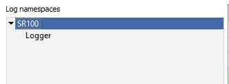
3.2 Log NameSpaces
Purpose: Allows users to select different namespaces related to supported chips and cores, facilitating targeted logging sessions specific to hardware components.
Functionality:
Currently, the tool supports logging for the SR110 chip with core M55, M4, with the potential to expand to other chips and cores in the future.
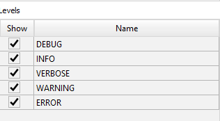
3.3 Levels
Purpose: Provides a customizable logging experience by allowing users to select which levels of log messages (such as Errors, Warnings, or Debug information) are visible.
Features:
Selective Visibility: Toggle visibility of log messages by level to focus on relevant data, such as debugging information or errors.
Customize Appearance: Modify the appearance of log messages by level for better readability or personal preference.
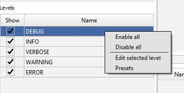
If you focus on one of the level with mouse and press right button the new windows will be popup where you can select one of options:
3.3.1 Enabling/Disabling Levels
Access: Right-click on any level in the levels window to access options.
Options:
Enable All: Show all log levels.
Disable All: Hide all log levels.
Edit Selected Level: Open the level editor to change properties such as color and font style.
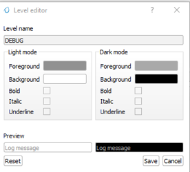
3.3.2 Level Editor
Functionality: Customize the visual properties of log messages for each level.
Settings:
Light/Dark Mode Color Settings: Adjust text and background colors for both light and dark modes.
Font Styles: Change font styles including bold, italic, and underline.
Preview: View changes in real-time within the preview pane at the bottom of the level editor window.
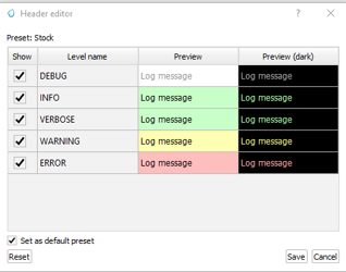
3.3.3 Presets
Purpose: Quickly apply predefined or custom styling presets to log levels.
Usage:
Set as Default Preset: Apply the selected preset as the default for all log levels.
Reset to Default: Revert to the application’s default preset settings.
Usage Tips:
Utilize the log namespace feature to manage logs according to specific hardware components or software modules.
Adjust log levels to streamline the debugging process, focusing only on the necessary data.
Customize log appearance to differentiate between log types easily or match user preferences for an enhanced visual experience.
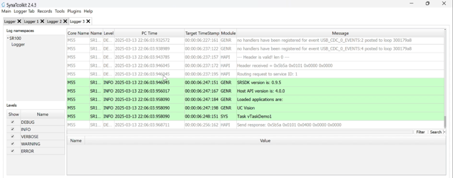
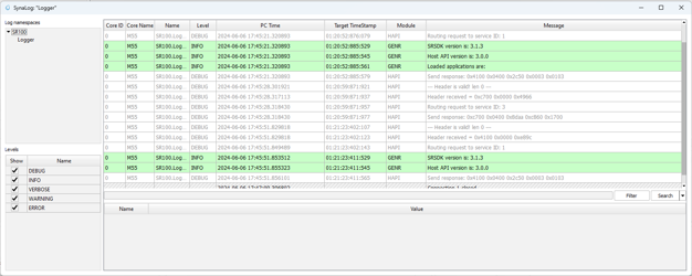
3.4 Main Log Window
Purpose: The Main Log Window is central to viewing and managing log data, offering a variety of tools to enhance the visibility and analysis of log messages.
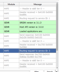
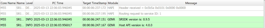
3.4.1 Log Display
Overview: Displays logs with detailed information such as Core Name, Log Namespace, PC Time, Target Timestamp, Module, and the message itself.
Navigation: Logs are shown in a tabulated format allowing for easy review and management.
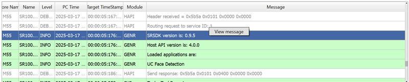
3.4.2 Message Details
Accessing Details: Right-click on a message and select “View message” to open a detailed view of the log message.
Usage: This feature is useful for examining complete log entries in depth.
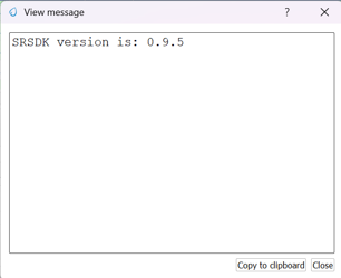
3.4.3 View Message Window
Functionality: Displays the complete content of a log message.
Options: Users can copy the message to the clipboard or close the window.
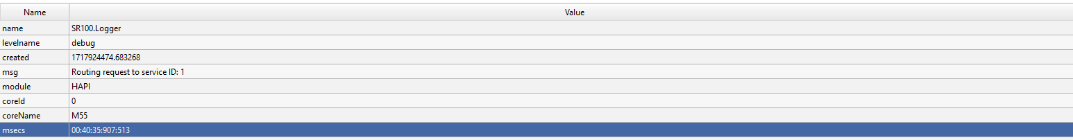
3.4.4 Parsed Message Display
Description: Shows a parsed view of the message, breaking down the log entry into its components like Name, Level, Time, and Message, among others.
Interactivity: This detailed view helps in understanding the structured components of each log message.
3.4.5 Filtering Logs
Filtering: Enter specific criteria in the filter bar to display only those log entries that meet the conditions.
Resetting Filter: Clear the filter by pressing the “Clear Filter” button to return to viewing all logs.
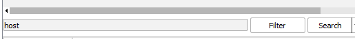

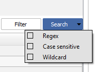
3.4.6 Search Functionality
Capabilities:
Regex (Regular Expression): Use regex for complex pattern searches within log messages.
Case Sensitive: Search the logs taking into account the case sensitivity.
Wildcard: Use wildcard characters to search for variations of a string.
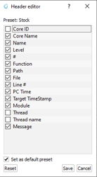
3.4.7 Customize Header
Customization: Right-click on any column header to customize which data columns are displayed.
Header Editor:
Adjust Visibility: Toggle various data points like Core ID, Function, Thread Name, etc., to show or hide in the log view.
Save/Reset: Save the custom settings as the default or reset to the stock configuration.

Tips for Effective Use:
Utilize the detailed message view to troubleshoot specific issues by examining the full content of relevant logs.
Regularly clear and filter logs to maintain clarity and focus on relevant entries during analysis.
Customize the log display headers to focus on information pertinent to your analysis needs.
4.0 SynaTool Commands Menu
4.1 ROM
4.1.1 Host API version
Purpose: This command allows users to retrieve the version number of the host API currently being used by the system, which can be crucial for compatibility checks and troubleshooting.
Command:
ver
Functionality:
Description: Executes the ver command to display the version of the host API.
Usage: Simply type ver in the command interface and press Enter. The API version will be displayed, providing you with the current version information of the host API.
4.1.2 Burn the file to flash
flashBurn <binary file>[sector addr offset in hex]
Usage:
flashburn B0_flash_full_image_GD25LE128_67Mhz_secured.bin
flashburn Model.bin 0x100000
4.1.3 Read Flash ID
Display the flash type and size
flashReadId
flashReadPage 0x400 - read the page that starts at address 0x400 (4th page in this example)
4.1.4 Erase Entire flash memory
CLI full command: flashChipErase
4.1.5 Erase Flash Sector
CLI full command: flashSectorErase <sector addr offset>[<Num of sectors>]
command example:
flashSectorErase 0x1000 - erases the sector that start with address 0x1000 (2nd sector in this example)
4.1.6 Use Alternative SPK/APBL Image for Burning
CLI full command: altSPK <binary File>
Using alternative SPK image: C:/Users/scorelen/Git/sabre_tool_kit/tools/srsdk_image_generator/B0_Input_examples/spk_rc3_0_nosecure_romk_dbg_0605.bin
Using alternative BootLoader image: D:/Synaptics/Apps/SynaToolkit_2.1.200/bin/Output/B0_Flash/Components/1_sr100_b0_bootloader_ver_0x0128_ASIC_flash_secured.bin
4.2 FW
4.2.1 Install the FW update
The fwUpdateInstall command installs and accepts the files that were updated on the flash memory. After executing this command, the ROM will load the newly updated module(s) from the flash.
Parameters:
reboot (optional): Specifies whether to reboot the system after installation. The default value is 0 (no reboot). Setting this parameter to 1 will reboot the
system.CLI full command: fwUpdateInstall [reboot]
Notes:
If no reboot parameter is provided, the system will not reboot by default.
4.2.2 FW Update
The FW Update command updates a specific module or multiple modules on the flash memory.
Steps to Use:
Use the image generator tool to build the image or multiple image files.
Execute the CLI command fwUpdate<binary file>
4.2.3 Burn the Flash
Choose the command, choose the file and press the “Execute” button.
The burn process should start
4.2.4 Read Flash ID
flashReadId - returns flash id with type and size
FlashType is: GIGADEVICE_GD25LQ128CD
FlashSize is: 128 Mbits
4.2.5 Erase a flash sector
The flashSectorErase command erases a specific sector or multiple sectors in the flash memory.
Parameters:
sector address: The address of the flash sector to be erased.
Num of sectors (optional): The number of consecutive sectors to be erased starting from the specified address. If not provided, only the specified sector will be erased.
CLI full command: flashSectorErase <sector address>[<Num of sectors>]
4.2.6 Read a flash memory page
The flashReadPage command reads the contents of a specified flash memory page.
Parameters:
page address: The address of the flash memory page to be read.
CLI full command: flashReadPage <page address>
Example: flashReadPage 0x1000