MIPI Doorbell ML Application
1. Overview
The Doorbell sample application integrates the UC_JPEG_PREROLL and IMAGE_STITCHING use cases to detect a person within the camera’s field of view and capture high-resolution Full HD (FHD) images upon detection.
1.1 Image Delivery Options
Captured images can be delivered in two ways:
Delivery Mode |
Description |
Tools for Visualization |
|---|---|---|
USB CDC (to Host PC) |
Sends images via USB CDC to a host PC. |
VS Code Extension |
SPI to Controller |
Sends images over SPI to another Astra Machina Eval Kit acting as a controller; receives frames for logging. |
Logger |
2. Build Instructions
2.1 Prerequisites
2.2 Build Options
Method |
Steps |
Notes |
|---|---|---|
VS Code Extension |
Import SDK → Build or Clean SDK in “Imported Repos” → select configs (Application, Board, Compiler) → Build |
GUI workflow; logs appear in VS Code terminal. |
Native CLI |
Run |
Suitable for native builds |
Configuration and Build Steps
Note: Configure WAKEUP_TRIGGER
Navigate to: uc_jpeg_preroll.c change to CONFIG_WAKEUP_TRIGGER set to 2 for (GPIO-based wakeup)
1. Using Astra MCU SDK VS Code extension
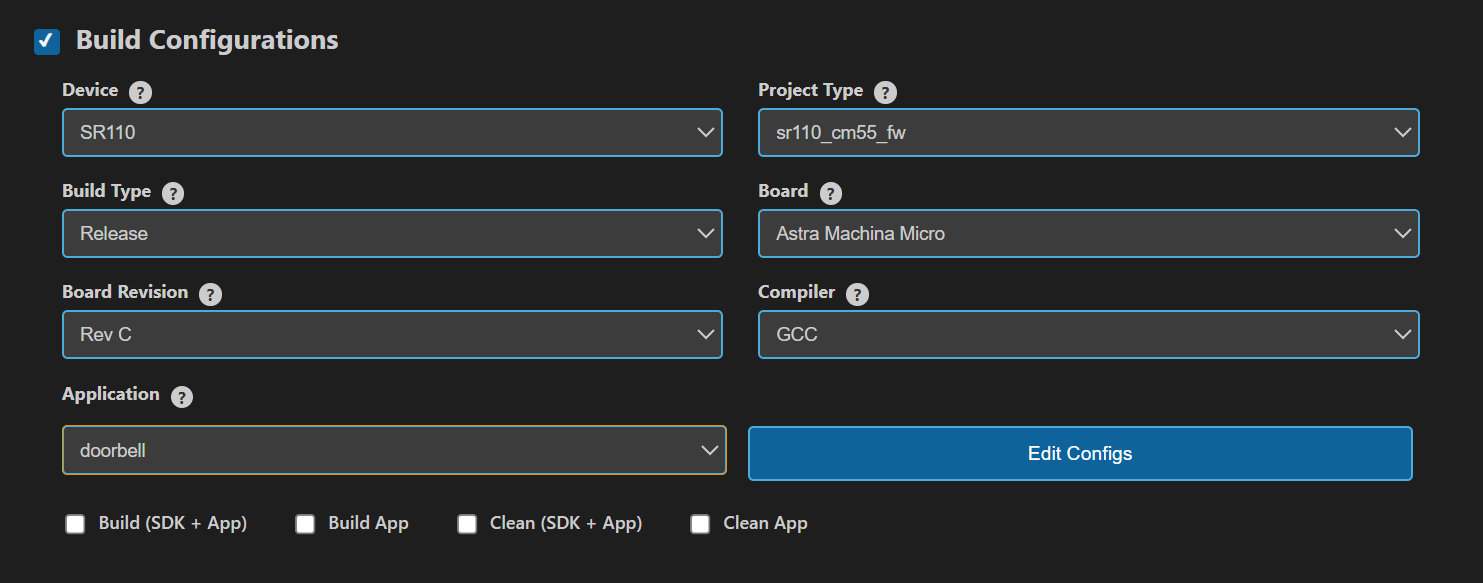
Navigate to IMPORTED REPOS → Build and Deploy in the Astra MCU SDK VS Code Extension.
Select the Build Configurations checkbox, then select the necessary options.
Select doorbell in the Application dropdown. This will apply the defconfig.
Select the appropriate build and clean options from the checkboxes. Then click Run. This will build the SDK generating the required
.elfor.axffiles for deployment using the installed package.
For detailed steps refer to the Astra MCU SDK VS Code Extension Userguide.
2. Native build in the terminal
Select Default Configuration and Build SDK + Example This will apply the defconfig, then build and install the SDK package, generating the required
.elfor.axffiles for deployment.make cm55_doorbell_defconfig BOARD=SR110_RDK BUILD=SRSDK
This configuration uses CONFIG_WAKEUP_TRIGGER set to 1 (Timer-based wakeup).
Rebuild the Application using pre-built package The build process will produce the necessary
.elfor.axffiles for deployment with the installed package.make cm55_doorbell_defconfig BOARD=SR110_RDK or make
3. Deployment and Execution
3.1 Setup and Flashing
Open the Astra MCU SDK VSCode Extension and connect to the Debug IC USB port on the Astra Machina Micro Kit. For detailed steps refer to the Astra MCU SDK User Guide.
Generate Binary Files
FW Binary generation
Navigate to IMPORTED REPOS → Build and Deploy in Astra MCU SDK VSCode Extension.
Select the Image Conversion option, browse and select the required .axf or .elf file. If the usecase is built using the VS Code extension, the file path will be automatically populated.
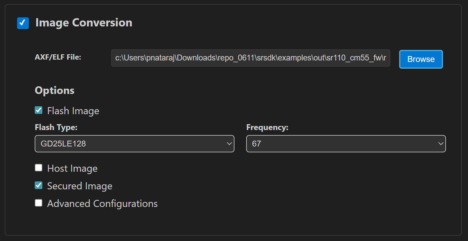
Click Run to create the binary files.
Refer to Astra MCU SDK VSCode Extension User Guide for more detailed instructions.
Model Binary generation (to place the Model in Flash)
To generate
.binfile for TFLite models, please refer to the Vela compilation guide.
Flash the Application
To flash the application:
Select the Image Flashing option in the Build and Deploy view in the Astra MCU SDK VSCode Extension.
Select SWD/JTAG as the Interface.
Choose the respective image bins and click Run.
Flash the pre-generated model binary:
door_bell_flash(384x512).bin. Due to memory constraints, need to burn the Model weights to Flash.Location:
examples/SR110_RDK/vision_examples/uc_jpeg_preroll/models/Flash address:
0x629000Calculation Note: The flash address is determined by adding the
host_imagesize and theimage_offset_SDK_image_B_offsetparameter (defined inNVM_data.json). Ensure the resulting address is aligned to a sector boundary (a multiple of 4096 bytes). This calculated address should then be assigned to theimage_offset_Model_A_offsetmacro in yourNVM_data.jsonfile.
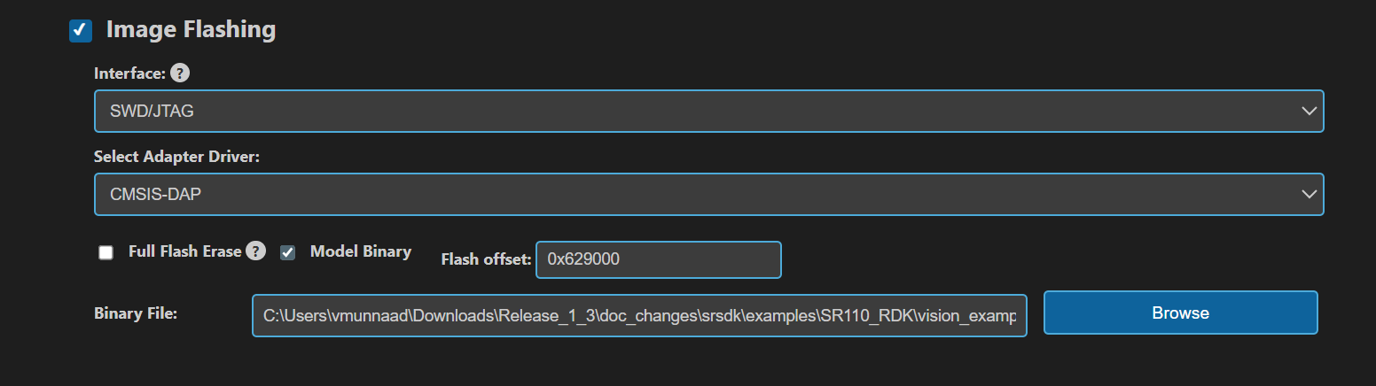
Note: By default, flashing a binary performs a sector erase based on the binary size. To erase the entire flash memory, enable the Full Flash Erase checkbox. When this option is selected along with a binary file, the tool first performs a full flash erase before flashing the binary. If the checkbox is selected without specifying a binary, only a full flash erase operation will be executed.
Refer to the Astra MCU SDK VSCode Extension User Guide for detailed instructions on flashing.
Note:
The placement of the model (in SRAM or FLASH) is determined by its memory requirements. Models that exceed the available SRAM capacity, considering factors like their weights and the necessary tensor arena for inference, will be stored in FLASH.
4. Running the Application
4.1 Options
Method |
Steps |
|---|---|
VS Code Extension |
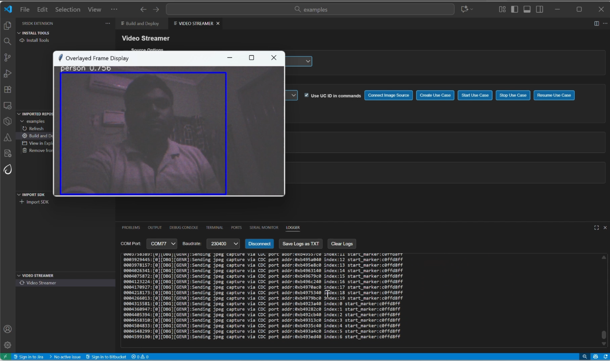
Open |
The video stream automatically appears whenever a person is detected.
💡 You can find detailed setup and usage instructions in the Astra MCU SDK VSCode Extension User Guide.
Initial Setup
Press
RSTNbutton onSR110_RDK.
Operation Flow
On detection → frame is streamed → device enters hibernation.
4.2 Wakeup Triggers
Trigger |
Config |
Behavior |
|---|---|---|
Timer |
|
Device wakes every 10 seconds. |
GPIO |
|
Jumper from GND → UART0 RX after 10s of hibernation. |
4.3 Result
The JPEG preroll images and high-resolution Full HD (FHD) images upon detection are saved in the overlayed_frames subfolder within the video_stream_output directory.Example: "C:\Users\<username>\video_stream_output" or "/home/User/video_stream_output"
5. SPI Pre-roll Use Case
5.1 Overview
The SPI Pre-roll feature enables UC_JPEG_PREROLL to capture JPEG pre-roll frames and stream them to a controller (receiver) over SPI.
Peripheral (Sender): The device that’s flashed with UC_JPEG_PREROLL acts as the SPI Peripheral device, that captures frames, packages them with headers/footers, and transmits them via SPI.
Controller (Receiver): The device that’s flashed with SPI_SAMPLE_APP acts as the SPI Controller device, that requests pre-roll frames, and validates CRC.
This mechanism ensures that when detection is triggered, the system can send pre-roll images that occurred before the detection event.
The SPI Pre-roll transfer follows a protocol as described in SPI Pre-roll Protocol
5.2 Configurations
5.2.1 Peripheral (Sender) Configurations
Run the Doorbell defconfig to apply the default settings for the doorbell use case. Enable SPI module by enabling MODULE_SPI_ENABLED and build the image. With the settings, the device will operate as the SPI pre-roll Peripheral (Sender).
make cm55_doorbell_defconfig BOARD=SR110_RDK BUILD=SRSDK EDIT=1 #Enable SPI and LOGGER_IF_UART_0
Remember enable LOGGER_IF_UART_0 before building the peripheral image with LOGGER_IF_UART_0 in the menuconfig.
5.2.2 Controller (Receiver) Configurations
Run the SPI Sample App defconfig to apply the default settings for the SPI Sample application.
Enable SPI_PREROLL_TRANSFER in spi_sample_app.c and SPI_DOUBLE_BOARD_MODE
in spi_sample_app.h and build the image.
With these settings, the device will operate as the SPI pre-roll Controller (Receiver).
make cm55_spi_sample_app_defconfig BOARD=SR110_RDK BUILD=SRSDK
make
5.3 Hardware Setup
The following are the pins that are used for SPI Communication,
5.3.1 Controller Pins
Pin 11 - SPI_MSTR_CLK (GPIO_22)
Pin 12 - SPI_MSTR_CS (GPIO_21)
Pin 13 - SPI_MSTR_MISO (GPIO_24)
Pin 14 - SPI_MSTR_MOSI (GPIO_23)
5.3.2 Peripheral Pins
Pin 7 - SPI_SLV_CLK (GPIO_6)
pin 8 - SPI_SLC_CS (GPIO_8)
pin 9 - SPI_SLV_MISO (GPIO_7)
pin 10 - SPI_SLV_MOSI (GPIO_9)
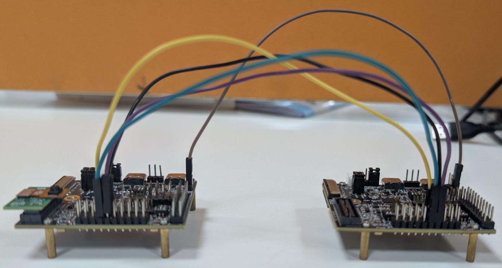
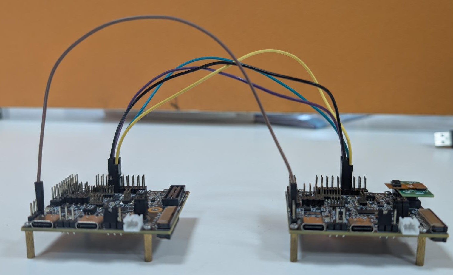
5.3.3 Connections
Pin 11 (SPI_MSTR_CLK) → Pin 7 (SPI_SLV_CLK)
Pin 12 (SPI_MSTR_CS) → Pin 8 (SPI_SLV_CS)
Pin 13 (SPI_MSTR_MISO) → Pin 9 (SPI_SLV_MISO)
Pin 14 (SPI_MSTR_MOSI) → Pin 10 (SPI_SLV_MOSI)
Remember, The logs will be seen via UART 0. Enable UART 0 log via menuconfig. It is recommended to have the DAP SR110 not powered up because of SPI pin conflict in RDK.
5.3.4 Connection Images
5.4 Test Procedure
The test can begin once the images are built, flashed onto the respective devices, and the hardware setup is completed. The pins described above represent the required SPI connections. In addition, the Ground lines of both boards must be connected to ensure a stable link. Failure to do so may result in corrupted or invalid data.
5.4.1 Peripheral (Sender) Steps
Before flashing the Peripheral image, the model binary must first be loaded at address 0x629000. Once the model is loaded, flash the Peripheral image and reset the device. On reset, the device enters hibernation and capture pre-roll images. Once the device wakes up from hibernation and if detection events are seen, It will initiate the SPI Peripheral Transfer to stream the captured pre-roll images.
5.4.2 Controller (Receiver) Steps
Flash the Controller image, but reset the controller device only after the peripheral wakes up from hibernation and begins the peripheral transfer. This ensures that the peripheral is ready to accept the pre-roll request and related commands from the controller.
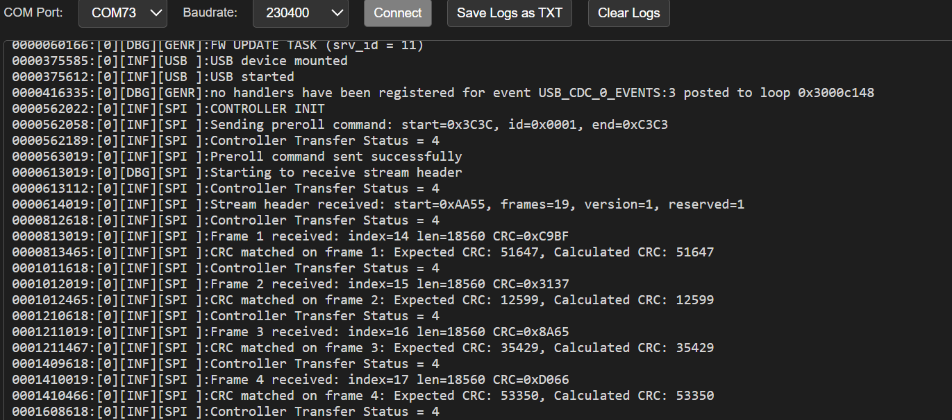
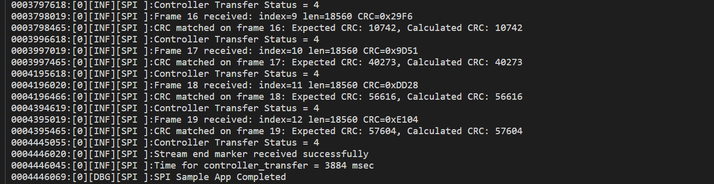
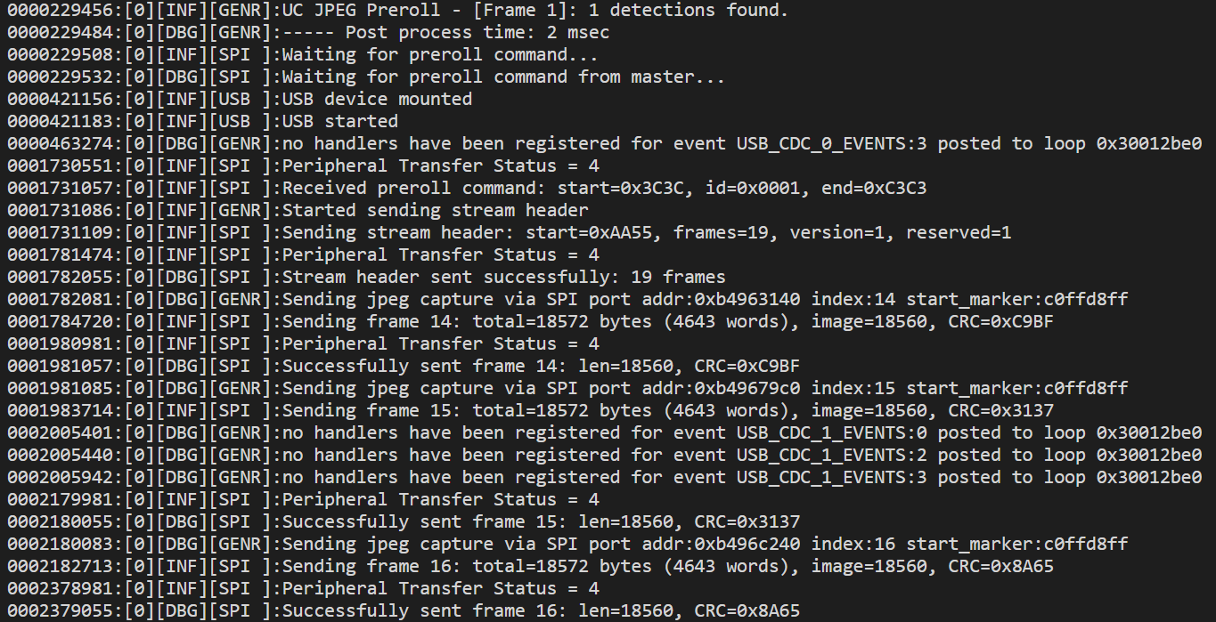
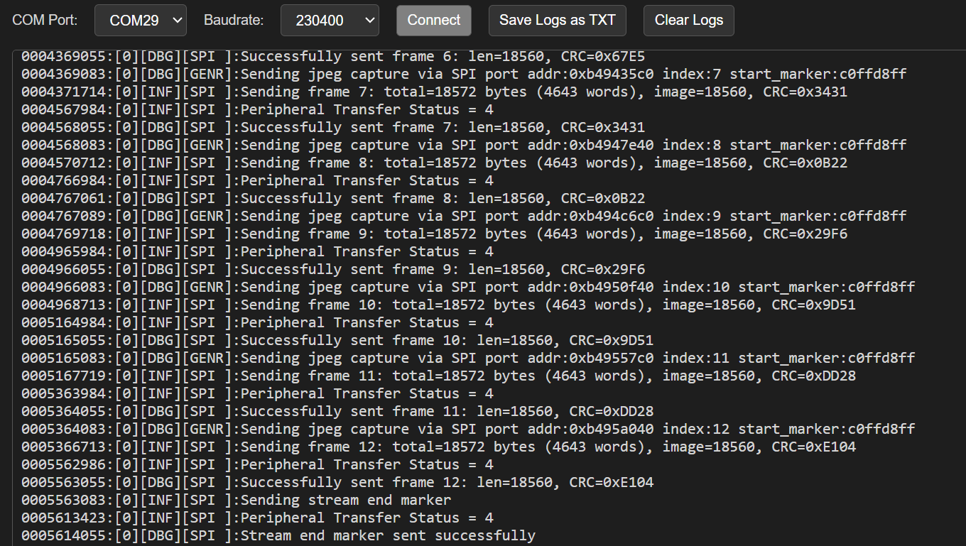
5.6 Expected Results
Controller initiates the transfer by sending a pre-roll request header. Peripheral responds with the stream header, all pre-roll JPEG frames, and the stream end marker over SPI. Controller successfully receives and validates each frame, including headers, CRC, and footers. We can confirm successful reception of pre-roll frames with logs.