SR110 Build and Flash with VS Code
This document provides concise, VS Code-only steps to build, convert images, flash, and debug SR110 applications. For common extension features (installation, tools, SDK import, logging, memory analysis), see Astra MCU SDK VS Code Extension User Guide.
Throughout this guide, <sdk-root> refers to the directory where you extracted or cloned the SDK.
Table of Contents
Prerequisites
Astra Machina Micro connected per the SR110 Platform Guide.
VS Code extension and tools installed. See Setup and Install SDK using VS Code.
Build and Deploy Flow
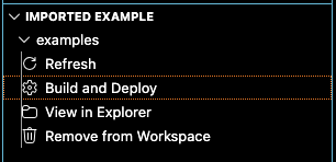
The Build and Deploy view allows running each step one at a time or sequentially.
If you check Build Configurations, Image Conversion, and Image Flashing, all three operations run sequentially. Each step automatically fills in required information for the next step, such as the .elf/.axf file or .bin file.
You may also run each step one at a time if desired.
The steps do not run until the Run button at the bottom of the view is pressed.
Environment Setup
Ensure the current working directory is the
<sdk-root>/examplesfolder. Select this via the Import Application/Example view.Set the workspace
SRSDK_DIRto<sdk-root>via the Import SDK view so the Build UI can detect the SDK.Open the Build and Deploy view in the Synaptics extension and set
Device→SR110.
Build Configurations (SR110)
Purpose: Generate .elf/.axf for SR110 firmware (cm55).
Steps:
Check the Build Configurations checkbox
Select the desired Build Mode:
Release for flashing
Debug for GDB debugging
Select the application from the Application dropdown.
Board Revision is printed on the bottom of Astra Machina Micro.
Choose the desired Compiler and Build Toolchain.
Enable the desired build and clean checkboxes
Build (SDK + App) builds and installs the SDK and builds the application.
Build App builds the application only and relies on previously installed SDK.
Result:
.axf/.bin files are written to
out/sr110_<Build_Type>/<Build_Mode>/sr110_<Build_Type>.elf/.axffor example out/sr110_cm55_fw/release/sr110_cm55_fw.elf.
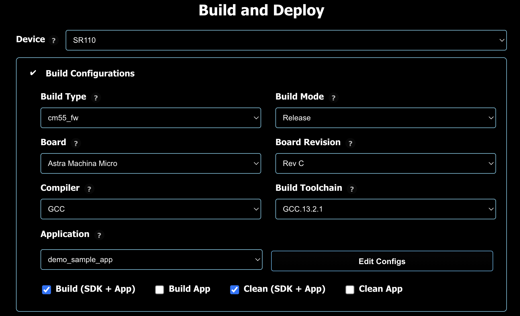
Image Conversion (SR110)
Purpose: Convert .axf/.elf outputs into flashable .bin images.
Steps (basic):
Check the Image Conversion checkbox.
The built .elf/.axf path is auto-populated after the build completes.
Select Flash Image
Select Secured
For flash images, choose Flash Type (default
GD25LE128) and Flash Frequency (default67).Click Run to convert.
Optional (advanced):
Convert a model bin when needed by selecting the model file and its security setting.
Result:
Converted binaries are written under
out/bin_files/Output/B0_Flash/B0_flash_full_image_GD25LE128_67Mhz_secured.bin
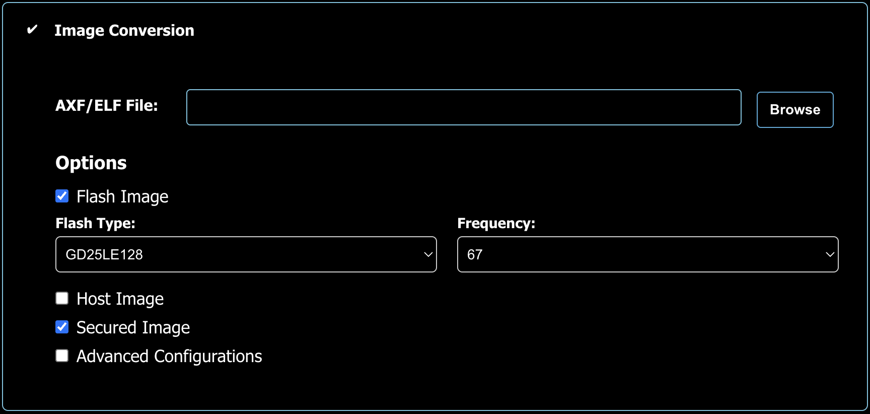
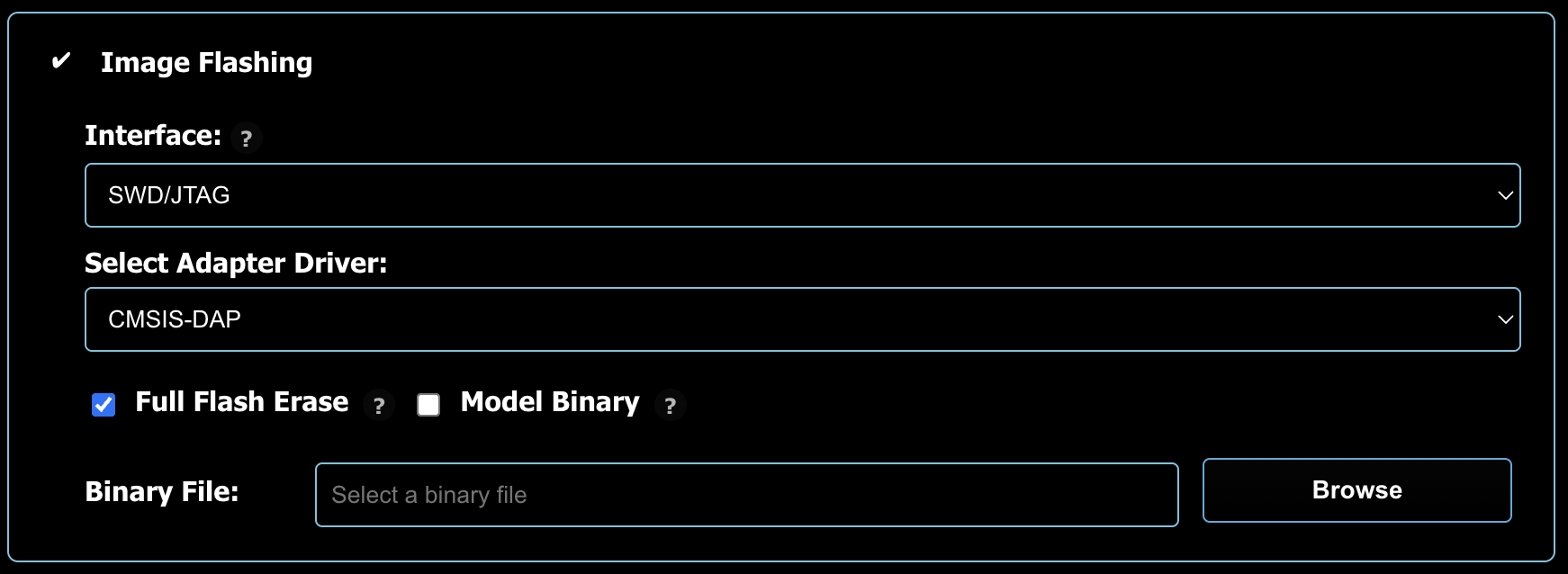
Image Flashing (SR110)
Check the Image Flashing checkbox.
If you are running WSL, please consult the Astra MCU SDK - WSL User Guide to ensure USB ports are properly handled.
Interface
There are three methods to update the flash connected to the SR110 on the Astra Machina Micro development kit.
SWD/JTAG (recommended for first use)
The Debug IC on the Astra Machina Micro is a CMSIS-DAP device. There is an SWD connection between the Debug IC and the SR110 on the Astra Machina Micro. The CMSIS-DAP device translates USB commands on J14 to SWD commands. Via SWD the external flash can be programmed.
Steps:
Ensure only J14 is connected
Open Image Flashing and select Interface →
SWD/JTAG.Select Select Adapter Driver →
CMSIS-DAP(onboard Debug IC) orJ-Link.Enable Full Flash Erase if you need a clean flash.
Confirm the auto-populated Binary File or browse to a
.bin.Click Run to flash.
Model binaries (vision examples):
If your application includes a model .bin, flash it using the Model Binary option and the offset specified by the example README (often 0x629000 for VGA use cases)
FW mode (UART/CDC)
This is the device firmware update (DFU) mechanism. For this method to work an image with the Host API and FW Update enabled must be running on the SR110. By default the communication protocol is USB CDC. This USB CDC enumerates on J13 of the Astra Machina Micro.
Plug J13 into the Astra Machina Micro and press reset.
Open Image Flashing and select Interface →
FW Update (Application Chip).Connect to the enumerated CDC Port.
Set Select Command to
Burn File to Flash.After flashing completes reset the SR110.
Note: For FW update, ensure only J13 is plugged in during the update process.
ROM
The SR110 has a ROM boot mechanism. To enable ROM boot the boot strap must be set properly.
On the Astra Machina Micro set SW1.2 in the “on” position, closer to the “KE” text on the switch.
After setting the boot strap reset the SR110.
Open Image Flashing and select Interface →
ROM.Connect an external USB to UART converter to J28.
Select the COM Port: that matches your external USB to UART converter.
After flashing is complete put SW1.2 back to off position and reset the SR110 to allow the code to run from external flash.
Advanced options
FW Update (Debug IC): This only needs to be run the first time you recieve the Astra Machina Micro or if the SDK ships with a new version.
In Advanced Options, select FW Update (Debug IC).
Choose the Debug IC COM port and select
tools/Debug_IC_FW/Debug_IC_FW.binClick Run, then unplug/replug the USB cable when finished.
Note: When updating Debug IC FW, ensure only J14 USB is plugged in.
Debugging (SR110)
Steps:
Build with Debug
Check the Debug Options and confirm the AXF/ELF path.
Select Adapter driver (
CMSIS-DAPorJ-Link) and keep Use default config file (or choose Provide custom config file to browse to a config).Choose Mode:
Download and Reset Program (typical)
Attach to Running Program
Attach and Halt Program
Click Run to start the debugger.
Running Examples
After flashing, reset the board and follow the example README for runtime instructions.
USB CDC Image Streaming (Windows)
Some vision examples stream image data over USB CDC. On Windows, install the correct driver for the streaming port. These steps will only work once a Vision example has been flashed onto the SR110. After flashing the vison example into the SR110 ensure both J14 and J13 USB are plugged in and reset the board.
Hardware setup:
Connect J13 for streaming
Keep J14 connected for power and console
Driver setup (Zadig):
Download Zadig from https://zadig.akeo.ie/.
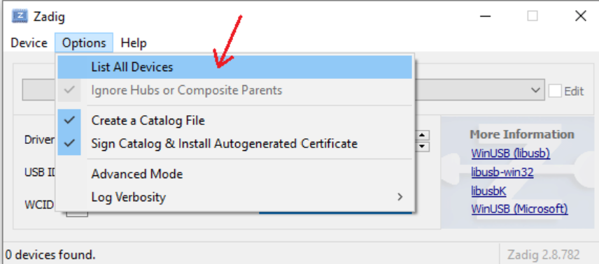
Run
zadig-2.8.exe.From Options, select List All Devices.
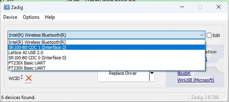
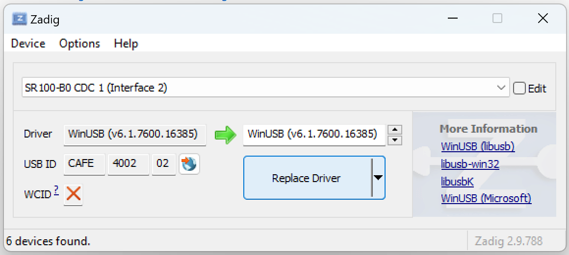
In the device dropdown, select SR 100-B0 CDC 1.
Choose WinUSB as the driver and click Replace Driver.
Reconnect the board and verify streaming in your example.