Person Pose Detection ML Application
Description
The UC Person Pose Detection application detects individuals in the camera’s field of view by generating bounding boxes and identifying 17 keypoints for each person, corresponding to various body parts. Each keypoint is accompanied by a confidence score that indicates the reliability of the detection, enabling accurate estimation of the person’s pose. This example supports both WQVGA(480x270) and VGA(640x480) resolutions.
Build Instructions
Prerequisites
Configuration and Build Steps
1. Using Astra MCU SDK VS Code extension
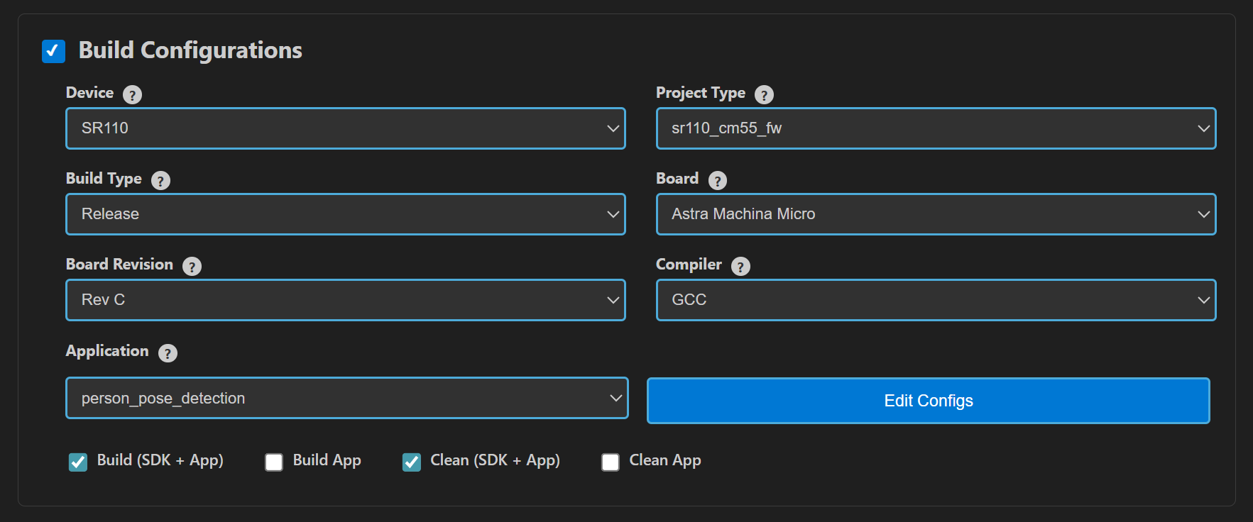
Navigate to IMPORTED REPOS → Build and Deploy in the Astra MCU SDK VSCode Extension.
Select the Build Configurations checkbox, then select the necessary options.
Select person_pose_detection in the Application dropdown. This will apply the defconfig.
Select the appropriate build and clean options from the checkboxes. Then click Run. This will build the SDK generating the required
.elfor.axffiles for deployment using the installed package.
For detailed steps refer to the Astra MCU SDK VS Code Extension Userguide.
2. Native build in the terminal
Select Default Configuration and build sdk + example This will apply the defconfig, then build and install the SDK package, generating the required
.elfor.axffiles for deployment using the installed package.make cm55_person_pose_detection_defconfig BOARD=SR110_RDK BUILD=SRSDK
This configuration uses WQVGA resolution by default.
Edit default configs and build sdk + example
💡Tip: Run
make cm55_person_pose_detection_defconfig BOARD=SR110_RDK BUILD=SRSDK EDIT=1to modify the configuration via a GUI and proceed with build.Configuration
Menu Navigation
Action
VGA Resolution
COMPONENTS CONFIGURATION → Off Chip Components → Display ResolutionChange to
VGA(640x480)WQVGA in LP Sense
COMPONENTS CONFIGURATION → DriversEnable
MODULE_LP_SENSE_ENABLEDStatic Image
COMPONENTS CONFIGURATION → Off Chip ComponentsDisable
MODULE_IMAGE_SENSOR_ENABLEDRebuild the Application using pre-built package The build process will produce the necessary .elf or .axf files for deployment with the installed package.
make cm55_person_pose_detection_defconfig BOARD=SR110_RDK or make
Note: We need to have the pre-built Astra MCU SDK package before triggering the example alone build.
Deployment and Execution
Setup and Flashing
Open the VSCode Astra MCU SDK Extension and connect to the Debug IC USB port on the Astra Machina Micro Kit. For detailed steps refer to the Astra MCU SDK User Guide.
Generate Binary Files
FW Binary generation
Navigate to IMPORTED REPOS → Build and Deploy in Astra MCU SDK VSCode Extension.
Select the Image Conversion option, browse and select the required .axf or .elf file. If the usecase is built using the VS Code extension, the file path will be automatically populated.
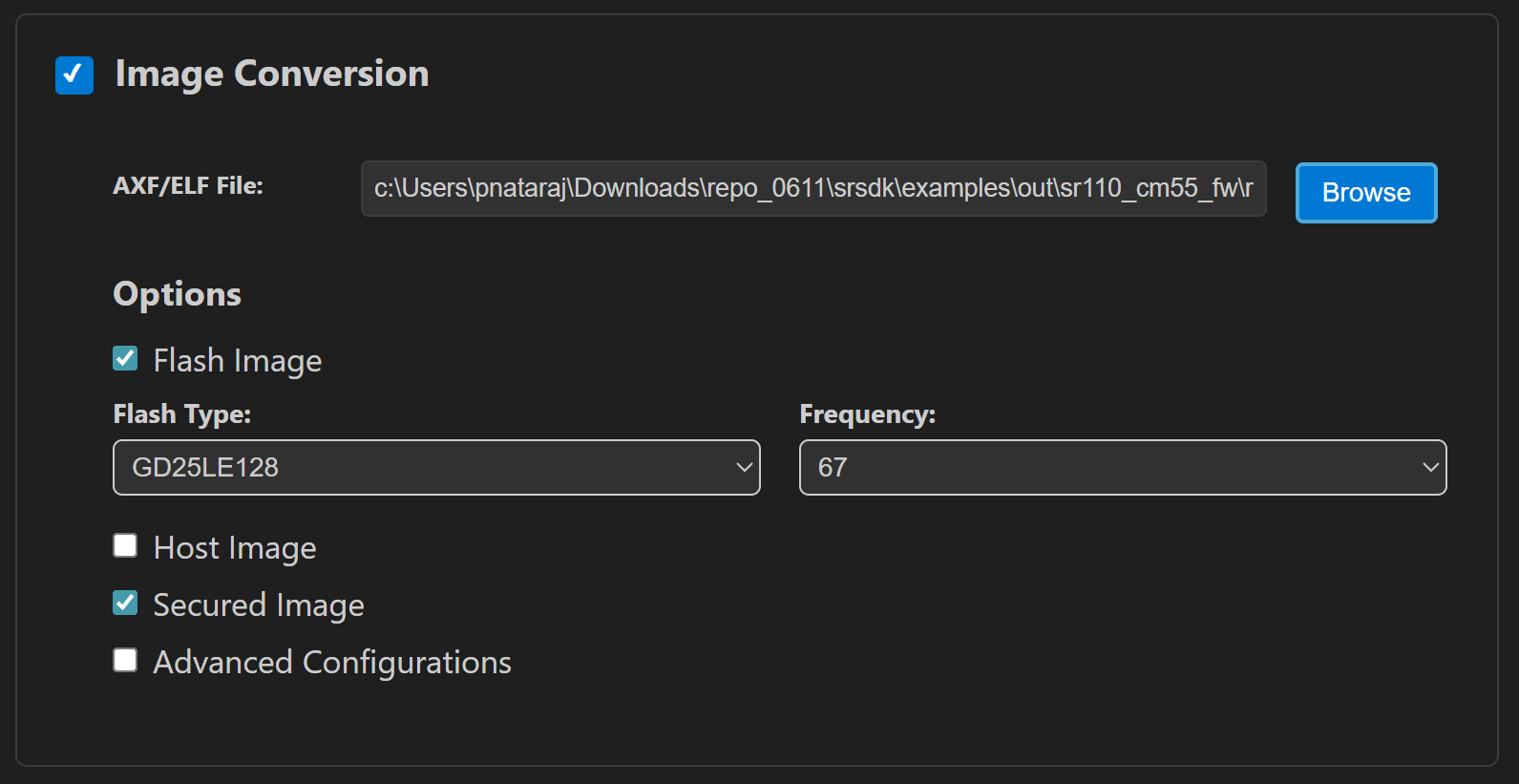
Click Run to create the binary files.
Refer to Astra MCU SDK VSCode Extension User Guide for more detailed instructions.
Model Binary generation (to place the Model in Flash)
To generate
.binfile for TFLite models, please refer to the Vela compilation guide.
Flash the Application
To flash the application:
Select the Image Flashing option in the Build and Deploy view in the Astra MCU SDK VSCode Extension.
Select SWD/JTAG as the Interface.
Choose the respective image bins and click Run.
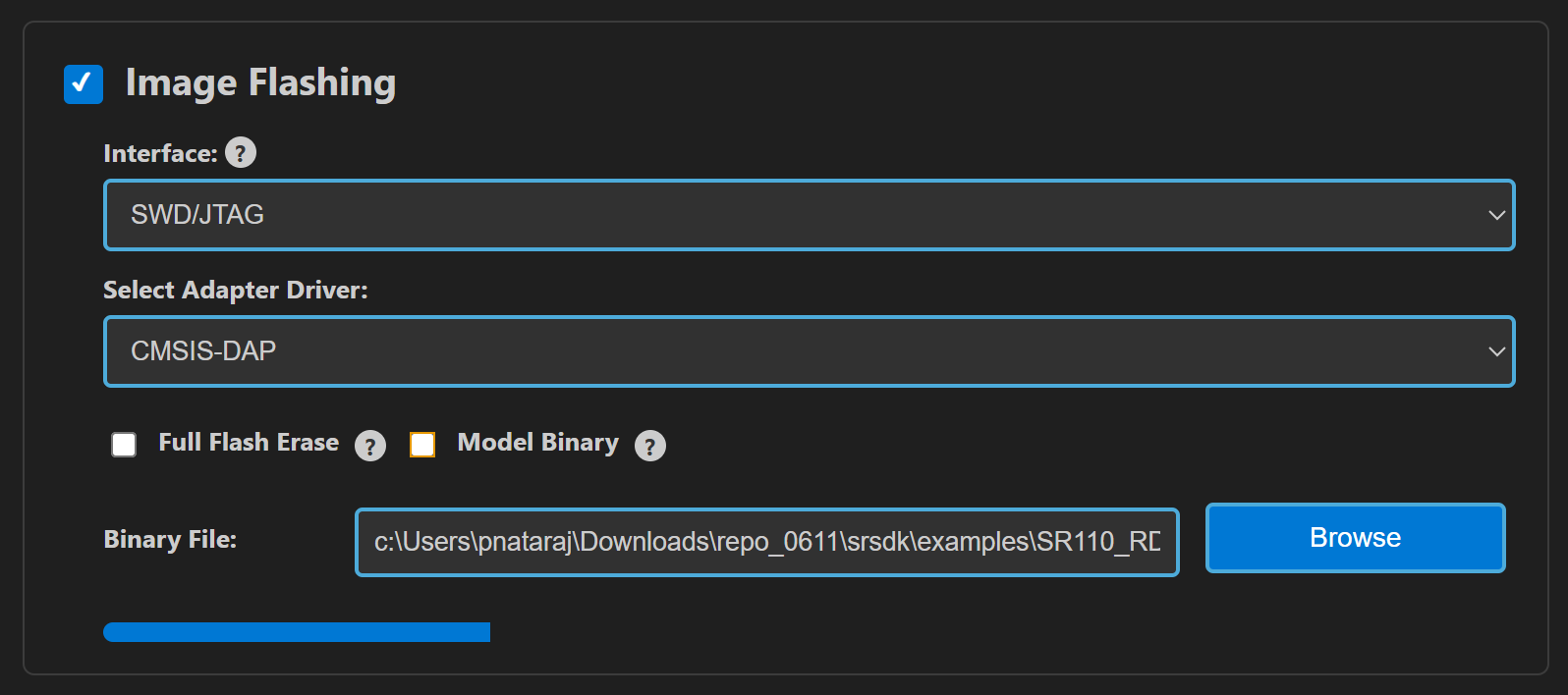
For WQVGA resolution:
Flash the generated
B0_flash_full_image_GD25LE128_67Mhz_secured.binfile directly to the device.
Note: Model weights is placed in SRAM.
For VGA resolution:
For VGA resolution, flash the model binary first, and then proceed to flash the generated use case binary.
Steps:
Flash the pre-generated model binary:
person_pose_detection(448x640).bin. Due to memory constraints, the model weights need to be stored in Flash. Browse and select this binary from the location:examples/vision_examples/uc_person_pose_detection/models/Select the Model Binary checkbox and enter the specified flash address in the “Flash Offset” field and start flashing.Flash address:
0x629000Calculation Note: The flash address is determined by adding the
host_imagesize and theimage_offset_SDK_image_B_offsetparameter (defined inNVM_data.json). Ensure the resulting address is aligned to a sector boundary (a multiple of 4096 bytes). This calculated address should then be assigned to theimage_offset_Model_A_offsetmacro in yourNVM_data.jsonfile.
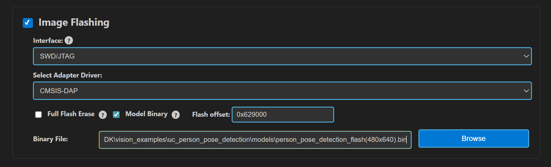
Flash the generated
B0_flash_full_image_GD25LE128_67Mhz_secured.binfile.
Note: By default, flashing a binary performs a sector erase based on the binary size. To erase the entire flash memory, enable the Full Flash Erase checkbox. When this option is selected along with a binary file, the tool first performs a full flash erase before flashing the binary. If the checkbox is selected without specifying a binary, only a full flash erase operation will be executed.
Refer to the Astra MCU SDK VSCode Extension User Guide for detailed instructions on flashing.
Device Reset
Reset the target device after flashing is complete.
Note:
The placement of the model (in SRAM or FLASH) is determined by its memory requirements. Models that exceed the available SRAM capacity, considering factors like their weights and the necessary tensor arena for inference, will be stored in FLASH.
Running the Application using VS Code extension
After successfully flashing the usecase and model binaries, click on Video Streamer option in the side panel. This will open the Video Streamer webview.
Before running the application, make sure to connect a USB cable to the Application SR110 USB port on the Astra Machina Micro board and then press the reset button
Select the newly enumerated COM port in the dropdown.
For logging output, click on SERIAL MONITOR and connect to the DAP logger port.
Select PERSON_POSE_DETECTION from the UC ID dropdown. Select RGB Demosaic: BayerRGGB
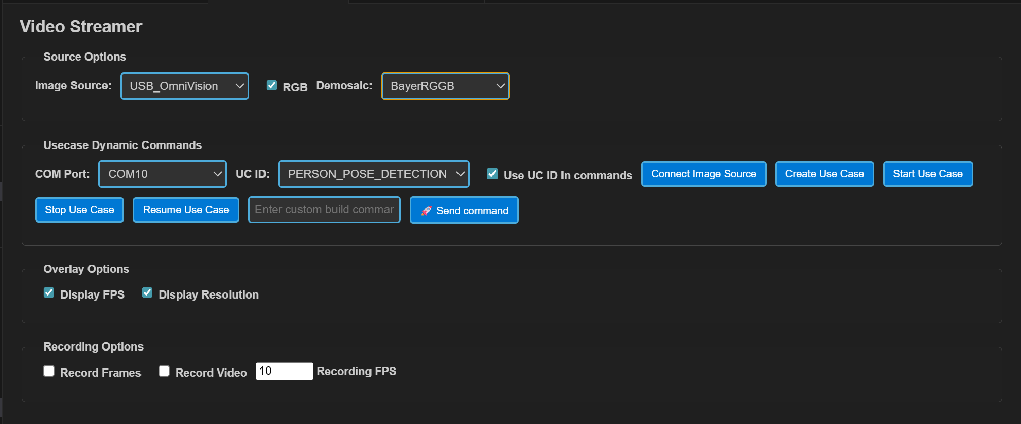
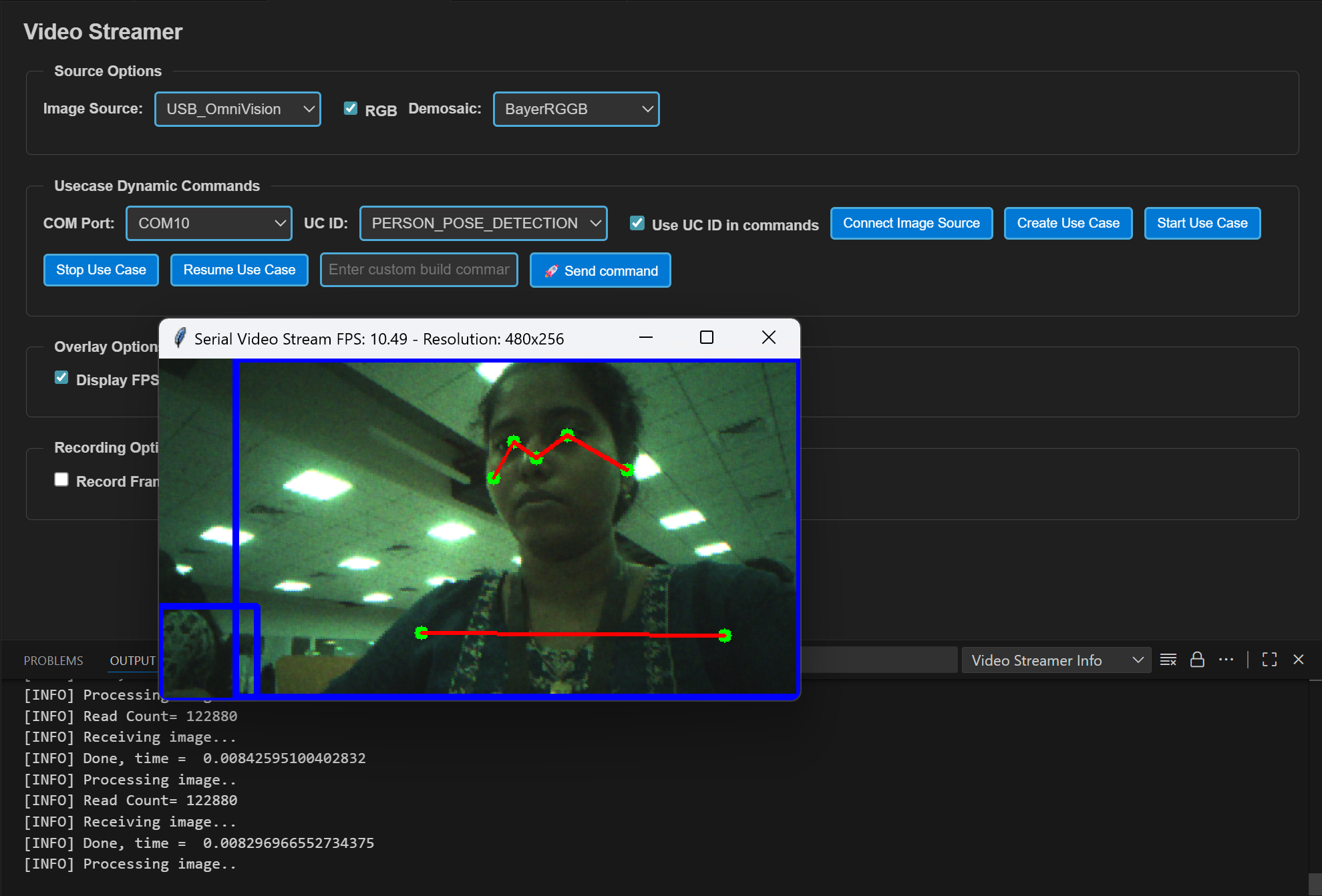
Click Create Use Case button. Then click the Start Use Case button. A python window will be opened and video stream will be displayed. Logs can be viewed through the Serial Monitor
Autorun usecases: If the usecase is built with autorun enabled, after flashing the binary and completing step 3 (selecting the usecase from the UC ID dropdown), click on the Connect Image Source button. This will open the video stream pop-up.