SPWM Driver Sample Application
Description
The SPWM Driver sample application demonstrates advanced pulse-width modulation and timing control on the supported boards for this application. It performs comprehensive SPWM testing including timer operations, PWM generation, capture functionality, and descriptor-based waveform generation to ensure precise timing control.
The sample includes multiple SPWM operations:
Timer operations: Configurable timer modes with interrupt generation and callback handling.
Capture functionality: Timer + capture mode for precise signal measurement and timing analysis.
PWM generation: Normal PWM mode with configurable frequency and duty cycle control.
PWM with dead-time: PWM_DT mode for motor control applications requiring complementary signals.
Pseudo-random PWM: PWM_PR mode for electromagnetic interference reduction in power electronics.
Descriptor-based generation: Advanced waveform generation using descriptor chains for complex burst patterns.
During each run, the app logs initialization status, configuration parameters, waveform generation progress, and validation results. This makes it easy for end users to confirm that SPWM setup and timing operations are working as expected.
The latest example structure uses a common application source tree with board-specific hardware setup kept under hw/<BOARD>/. For this app:
Common application sources such as
main.c,spwm_sample_app.c, andspwm_sample_app.hstay in the app root.Application defconfigs are stored under
configs/.Board and hardware-specific setup is selected from
hw/<BOARD>/, for examplehw/SL2610_RDK/.
The application can also be exported and built as a standalone app repository. In that flow, keep this app in its own directory, point SRSDK_DIR to the SDK root, and build from the app directory itself. For the full application workflow model, see Astra MCU SDK User Guide.
Supported Boards
This application supports:
SL2610_RDK
Select the defconfig that matches your target board and the desired SPWM mode, and the build system will pick the corresponding board-specific hardware setup from hw/<BOARD>/.
Prerequisites
Choose one setup path:
Test Case Selection
Before building, choose the testcase defconfig that matches both your target board and the SPWM mode you want to validate.
You can:
Select the required defconfig directly from the application’s
configs/directory.Run
make list_defconfigsfrom the application directory to list all supported defconfigs.
Available defconfigs:
sl2610_rdk_cm52_spwm_capture_mode_defconfigsl2610_rdk_cm52_spwm_pwm_deadtime_mode_defconfigsl2610_rdk_cm52_spwm_pwm_desc_mode_defconfigsl2610_rdk_cm52_spwm_pwm_mode_defconfigsl2610_rdk_cm52_spwm_pwm_pseudo_random_mode_defconfigsl2610_rdk_cm52_spwm_timer_mode_defconfig
For this app, the default defconfig is:
sl2610_rdk_cm52_spwm_timer_mode_defconfig
Building and Flashing the Example using VS Code
Use the VS Code flow described in the respective soc vscode guides and the VS Code Extension guide:
Build (VS Code):
Open Build and Deploy -> Build Configurations.
Select the spwm_sample_app project configuration in the Project Configuration dropdown.
Select the required defconfig for the application (timer, pwm, capture, etc.).
Build with Build (SDK+Project) for the first build, or Build (Project) for rebuilds.
Flash (VS Code):
Use the SL2610 image-generation flow to generate the required sub-image.
Open Image Flashing (SL2610).
Select Flash Target as M52 Image.
In Image Path, browse to and select the generated sub-image file, such as
sysmgr.subimg.gz.Start the flashing operation to program the image to the target.
Building and Flashing the Example using CLI
Use the CLI flow described in the respective build guide:
Build (CLI):
Build from the application directory itself:
cd <sdk-root>/examples/driver_examples/spwm_sample_app
export SRSDK_DIR=<sdk-root>
make <app_defconfig> BUILD=SRSDK
For faster rebuilds when only app code changes, reuse the app-local installed SDK package:
cd <sdk-root>/examples/driver_examples/spwm_sample_app
export SRSDK_DIR=<sdk-root>
make build
If this app has been exported to its own repository, use the same commands from that exported app directory after setting
SRSDK_DIRto the SDK root.
Build outputs (CLI):
Application binary:
<app-dir>/out/<target>/release/<target>.elfApp-local SDK package:
<app-dir>/install/<BOARD>/<BUILD_TYPE>/
Flash (CLI):
Flash SL2610
Build the SL2610 bootloader image.
cd <sdk-root>
export SRSDK_DIR=<sdk-root>
make <SL2610_Bootloader_defconfig> BOARD=<BOARD>
make astrasdk
Generate the system sub-image.
cd <sdk-root>/examples/driver_examples/spwm_sample_app
export SRSDK_DIR=<sdk-root>
make imagegen
Flash/download image to target.
Refer: SL2610 Platform Guide
Running the Application using VS Code Extension
Press RESET on the board after flashing.
For logging output, click SERIAL MONITOR and connect to the UART port.
Connect UART bridge to the target pins for serial communication
The logger port may vary across OSes, try different COM ports if needed
For PWM waveform observation, connect a logic analyzer to the required pins.
SPWM sample logs appear in the logger window, including configuration status and waveform generation results.
Sample applications logs and output
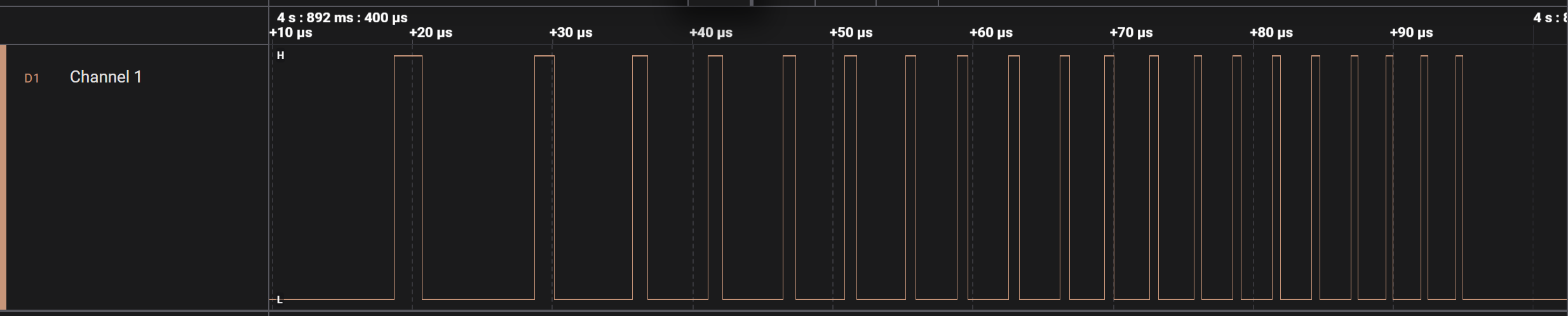
Timer Application
Console logs.
0000000000:[0][INF]▒▒0▒J:SPWM Timer Mode Starts (group 0)
0000000005:[0][INF]▒▒0▒J:CLKDIV[0] Setup: int_div=1 frac_div=0
0000000011:[0][INF]▒▒0▒J:INTERRUPT Setup: group=0 intr=1
0000000016:[0][INF]▒▒0▒J:[ISR] Callback triggered!
0000000016:[0][INF]▒▒0▒J:[ISR] Group 0: CC0 match
0000000016:[0][INF]▒▒0▒J:[ISR] Group 0: CC0 match
0000000022:[0][INF]▒▒0▒J:CC0 interrupt received, counter=3034
0000000028:[0][INF]▒▒0▒J:SPWM-Timer Sample App Completed (group 0)!
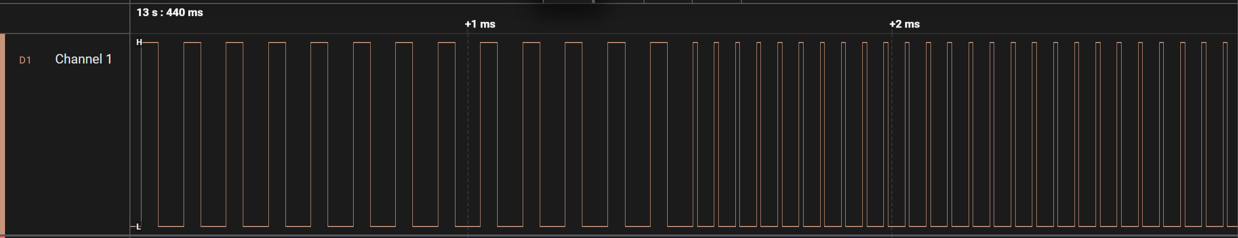
Timer + Capture Application
Console logs.
0000000000:[0][INF]▒▒0▒K:SPWM Timer + Capture App Starts
0000000005:[0][INF]▒▒0▒K:CLKDIV[0] Setup: int_div=1 frac_div=0
0000000011:[0][INF]▒▒0▒K:INTERRUPT Setup: group=0 intr=1
0000000016:[0][INF]▒▒0▒J:[ISR] Callback triggered!
0000000016:[0][INF]▒▒0▒K:[ISR] Group 0: CC0 match
0000000022:[0][INF]▒▒0▒K:Capture results: CC0=1108 CC1=1108
0000000027:[0][INF]▒▒0▒K:Capture successful
0000000031:[0][INF]▒▒0▒K:SPWM TIMER + CAPTURE Sample App Completed!
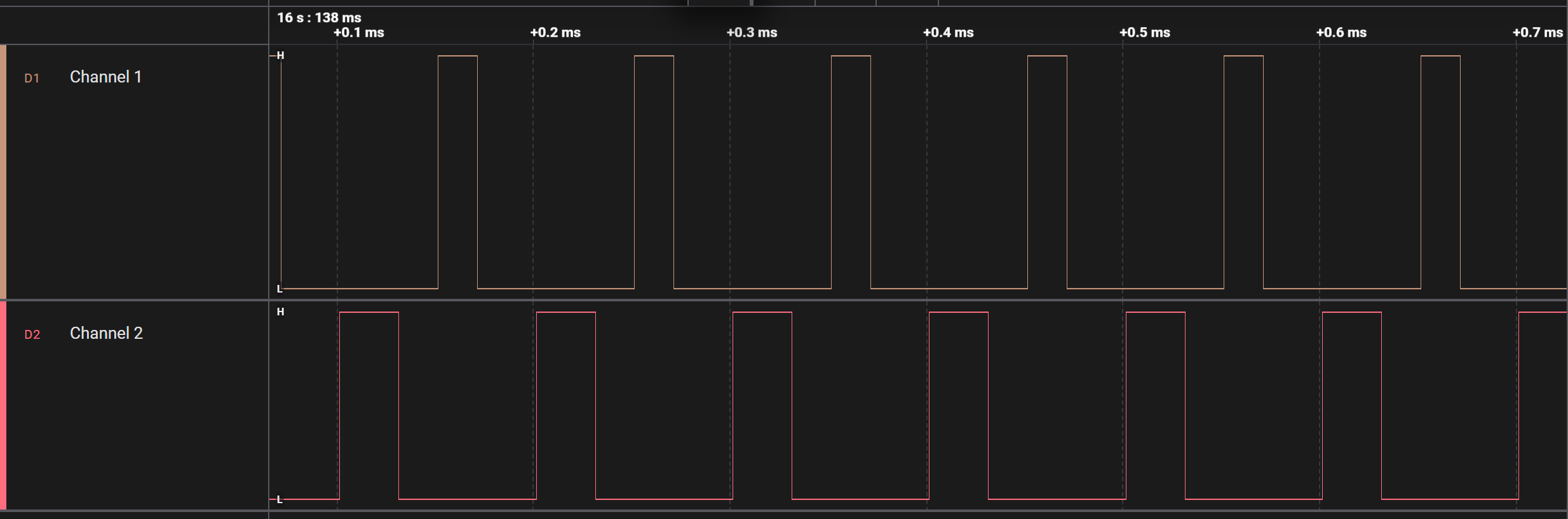
PWM Sample Application
Console logs.
0000000000:[0][INF]▒▒0▒G:SPWM PWM-Demo Starts
0000000004:[0][INF]▒▒0▒G:CLKDIV[0] Setup: int_div=1 frac_div=0
0000000010:[0][INF]▒▒0▒G:SPWM Group 0 Enabled
0000000014:[0][INF]▒▒0▒G:PWM started: Period=5000 CC0=1000
0000000020:[0][INF]▒▒0▒G:Duty = 20.0%
0000000023:[0][INF]▒▒0▒G:PWM Sample App Completed Successfully!
PWM with Deadtime Application
Console logs.
0000000000:[0][INF]▒▒0▒G:PWM-DT App Starts
0000000003:[0][INF]▒▒0▒G:CLKDIV[0] Setup: int_div=1 frac_div=0
0000000010:[0][INF]▒▒0▒G:PWM-Deadtime Sample App Completed!
PWM Pseudo Random Application
Console logs.
0000000000:[0][INF]▒▒0▒I:SPWM PWM Pseudo Random Mode Test Starts
0000000005:[0][INF]▒▒0▒I:CLKDIV[0] Setup: int_div=1 frac_div=0
0000000012:[0][INF]▒▒0▒I:INTERRUPT Setup: group=0 intr=1
0000000017:[0][INF]▒▒0▒I:PWM Pseudo Random Mode Sample App Completed!
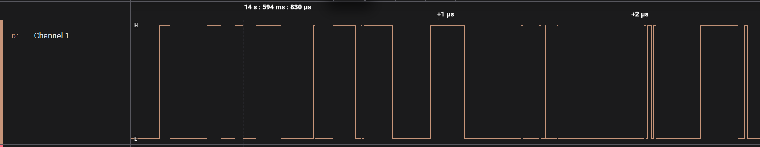
PWM Ramp signal with descriptors Application
Console logs.
0000000000:[0][INF]▒▒0▒R:  Step 0: Period=999 CC0=200 Cycles=1 (f=100000 Hz, duty=20.00%, ~11.2µs)
0000000008:[0][INF]▒▒0▒R:  Step 1: Period=699 CC0=140 Cycles=1 (f=142857 Hz, duty=20.00%, ~11.2µs)
0000000017:[0][INF]▒▒0▒R:  Step 2: Period=537 CC0=107 Cycles=2 (f=185874 Hz, duty=19.89%, ~11.2µs)
0000000026:[0][INF]▒▒0▒R:  Step 3: Period=436 CC0=87 Cycles=2 (f=228833 Hz, duty=19.91%, ~11.2µs)
0000000035:[0][INF]▒▒0▒R:  Step 4: Period=367 CC0=73 Cycles=3 (f=271739 Hz, duty=19.84%, ~11.2µs)
0000000044:[0][INF]▒▒0▒R:  Step 5: Period=317 CC0=63 Cycles=3 (f=314465 Hz, duty=19.81%, ~11.2µs)
0000000053:[0][INF]▒▒0▒R:  Step 6: Period=279 CC0=56 Cycles=4 (f=357143 Hz, duty=20.00%, ~11.2µs)
0000000062:[0][INF]▒▒0▒R:  Step 7: Period=249 CC0=50 Cycles=4 (f=400000 Hz, duty=20.00%, ~11.2µs)
0000000071:[0][INF]▒▒0▒R:PWM ramp: 8 steps, 20 total cycles, ~90 µs burst, 58 descriptors
0000000079:[0][INF]▒▒0▒R:CLKDIV[0] Setup: int_div=1 frac_div=0
0000000085:[0][INF]▒▒0▒R:Initial config: ACTIVE=[Period=10 CC1=2] BUFFER=[Period=999 CC1=200]
0000000093:[0][INF]▒▒0▒R:Building descriptor chain for configured burst time
0000000100:[0][INF]▒▒0▒R:Descriptor chain built with 58 descriptors
0000000107:[0][INF]▒▒0▒R:Descriptor 0 completed
0000000108:[0][INF]▒▒0▒R:PWM-Ramp started with the configured frequency and duty cycle
0000000116:[0][INF]▒▒0▒R:PWM-Ramp using Descriptor completed successfully!