SL2610 Build and Flash with VS Code
This document provides concise, VS Code-only steps to build, generate images, and flash SL2610 applications. For common extension features (installation, tools, SDK import, logging, memory analysis), see Astra MCU SDK VS Code Extension User Guide.
Throughout this guide, <sdk-root> refers to the directory where you extracted or cloned the SDK.
Table of Contents
Prerequisites
Development on SL2610 requires Linux. Windows users should run VS Code in Ubuntu 22.04 via WSL; see Astra MCU SDK - WSL User Guide. macOS support is planned for a future release.
SL2610 RDK connected with 5V USB-C power (PWR_IN) and USB 2.0 OTG to the host.
Ensure hardware connections are set up per the SL2610 Platform Guide.
VS Code extension and tools installed. See Setup and Install SDK using VS Code.
Build and Deploy Flow
The Build and Deploy view allows running each step one at a time or sequentially.
If you check Build Configurations, Image Generation (SL2610), and Image Flashing (SL2610), all three operations run sequentially. Each step automatically fills in required information for the next step, such as the .elf file or sub-image path.
You may also run each step one at a time if desired.
The steps do not run until the Run button at the bottom of the view is pressed.
Environment Setup
Import the SDK root and set workspace
SRSDK_DIRto<sdk-root>via the Import SDK view.Import the project you want to build via the Import Project view.
Open Build and Deploy from the Imported Projects view and set
Device->SL2610.If multiple projects are imported, select the correct project in the Build and Deploy project dropdown.
Build Configurations (SL2610)
Purpose: Generate .elf for SL2610 CM52 firmware.
Steps:
Check the Build Configurations checkbox.
If multiple projects are imported, select the correct project in the Build and Deploy project dropdown.
Set Build Configuration to
Release.Select the target Board and Compiler.
Set Build Toolchain to
GCC.13.2.1when the field is available.Select the desired Application from the dropdown.
Choose the appropriate build option:
Option |
What it does |
When to use it |
|---|---|---|
SDK Build (default_package) |
Generates the shared SDK foundation in |
Use this first to prepare the common SDK package required by project builds. |
Build (SDK+Project) |
Builds the SDK components required by the app based on the app configuration, installs them into the app-local install folder, and then builds the example using that generated install package. |
Use this when building an app for the first time and the required SDK components have not yet been generated for that app. |
Build (Project) |
Builds the active SL2610 project using project-local artifacts. |
Use this during normal development when you want a fresh build for the selected project. |
Build (Use Pre-built SDK) |
Builds the active SL2610 project against the common install root in |
Use this to reuse an existing SDK package and avoid rebuilding shared components. |
Notes:
SL2610 builds only support
Releasemode from the extension UI.If Build Configurations is disabled, verify that
SRSDK_DIRis set correctly through the Import SDK view.
Result:
Build outputs are generated under the project’s
out/sl2610_cm52_fw/release/directory, for exampleout/sl2610_cm52_fw/release/sl2610_cm52_fw.elf.
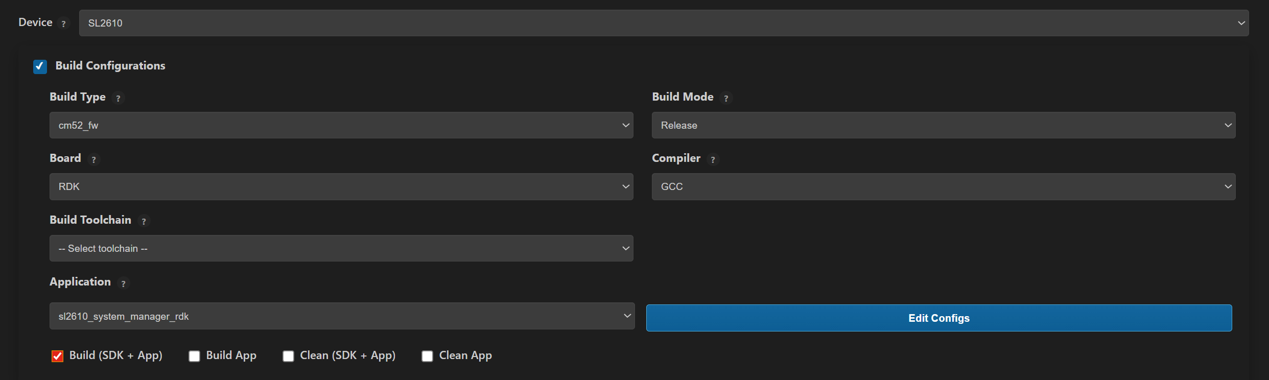
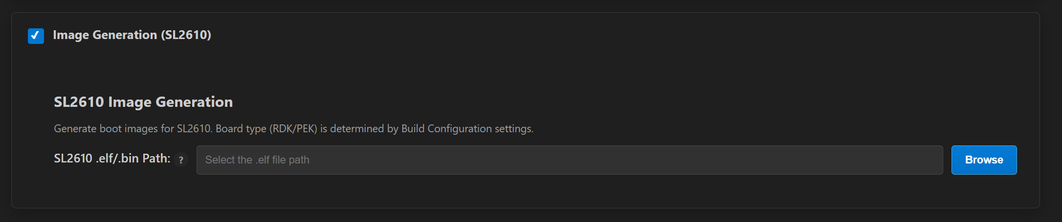
Image Generation (SL2610)
Purpose: Convert MCU executables (.elf) into System Manager sub-images and the xSPI NOR flash images.
Bootloader prerequisite:
Before generating an SL2610 image, build the SL2610_RDK bootloader once from the imported SDK folder in VS Code:
Open Build and Deploy for the imported SDK folder.
Set
Device->SL2610.In Build Configurations, select:
Build Target ->
bootloaderBuild Configuration ->
ReleaseBoard ->
SL2610_RDKCompiler and Build Toolchain as required by your environment
A matching
SL2610_RDKbootloader defconfig, for examplesl2610_bootloader_rdk_defconfig
Enable Build and click Run.
Bootloader result:
The bootloader build generates
out/sl2610_bootloader/release/sl2610_bootloader.elfunder the SDK root.This bootloader artifact is required by the SL2610 image-packaging flow.
Steps:
Open Build and Deploy for the imported SL2610 application project.
Check Image Generation (SL2610).
Use the Build and Deploy workflow to generate the image together with Build Configurations, or run Build Configurations once before image generation so the Release
.elfis available.Confirm the pre-populated Release build path or use Browse to select a custom MCU executable. Note: This path is automatically populated after the build completes.
Click Run. The extension uses the previously built
SL2610_RDKbootloader together with the application.elfto package the SL2610 image outputs.
Result:
The System Manager sub-image is generated under
out/image/eMMCimg/sysmgr.subimg.gz.The xSPI NOR flash image is generated under
out/image/XSPIimg/spi.bin.Additional image-packaging outputs are generated under
out/image/eMMCimg/,out/image/XSPIimg/, andout/image/USBimg/.
Note: Image Generation for SL2610 is available only on Linux platforms.
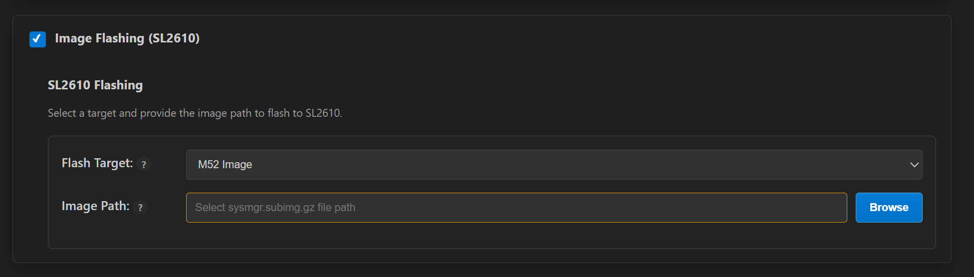
Image Flashing (SL2610)
Two supported methods:
Yocto-based flashing: Astra Yocto Linux docs
VS Code-based flashing (recommended for SL2610 development)
VS Code-Based Flashing
Before flashing, press and hold the USB_BOOT button, then press and release RESET.
If you are running WSL, please consult the Astra MCU SDK - WSL User Guide to ensure USB ports are properly handled.
Check Image Flashing (SL2610).
The Image Flashing panel exposes three fields you must configure:
Field |
Description |
|---|---|
Storage Type |
The destination flash on the board: |
Flash Target |
What to write to that storage. Available options depend on the selected Storage Type (see below). |
Image Path |
Path to the image (or image folder, for |
Flash Target options by Storage Type:
Storage Type |
Flash Target |
Meaning |
Expected Image Path |
|---|---|---|---|
|
M52 Image |
System Manager sub-image only |
|
|
Full Image |
Full eMMC image (GPT + partitions) |
eMMC folder containing |
|
xSPI NOR Image |
xSPI NOR flash image |
|
The supporting USB boot files (
key.bin,spk.bin,m52bl.bin,sysmgr.subimg) are auto-derived from the same image output folder, so you only need to specify the Image Path above.
Per-target details
eMMC → M52 Image — Provide the sysmgr sub-image path. Auto-populated after image generation; use Browse to select a custom sysmgr sub-image (typically
out/image/eMMCimg/sysmgr.subimg.gz).eMMC → Full Image — Provide the eMMC folder path that contains
emmc_part_listandemmc_image_list. The extension uses these files to determine partitions and image order for flashing.xSPI NOR → xSPI NOR Image — Provide the NOR flash image, typically
out/image/XSPIimg/spi.bin. Two optional erase modes are available:Full Flash Erase — Performs a full chip erase, then continues into flashing the provided
spi.bin(see Full Flash Erase (xSPI) below for the exact sequence).Erase Only — Performs a chip erase without flashing any image afterward.
Full Flash Erase (xSPI)
When the Full Flash Erase checkbox is selected during an xSPI NOR flash, the operation runs in two phases with a mandatory USB reset in between.
Sequence:
The xSPI flash chip is fully erased.
The extension pauses and waits for a USB reset — a prompt appears in VS Code.
Perform a USB reset on the board: press and hold USB_BOOT, then press and release RESET, then release USB_BOOT.
Acknowledge the prompt in VS Code. Flashing of
spi.binresumes automatically and runs to completion.
The USB reset is required because the chip-erase phase leaves the device in a state where it must re-enumerate before the flashing phase can proceed. Skipping or delaying the reset will cause the second phase to time out.
Debugging (SL2610)
Debugging is not yet supported in the VS Code extension for SL2610.
Running Examples
For instructions on how to run a specific example, see that example’s README.