Person Segmentation ML Application
Description
The UC Segmentation application is designed to detect and segment persons within the camera’s field of view. It generates pixel-wise masks that accurately outline each detected individual, along with corresponding bounding boxes and confidence scores. The output includes segmented regions that represent the exact shape of each person in the image, providing both spatial and confidence-level insights for each detection. This example supports both WQVGA(480x270) and VGA(640x480) resolutions.
Prerequisites
Choose one setup path:
Building and Flashing the Example using VS Code
Use the VS Code flow described in the SR110 guide and the VS Code Extension guide:
Build (VS Code):
Open Build and Deploy -> Build Configurations.
Select person_segmentation in the Application dropdown.
If you need VGA (640x480), click Edit Configs (Menuconfig) in the Build and Deploy view, then set
COMPONENTS CONFIGURATION -> Off Chip Components -> Display Resolutionto VGA.Optional configuration changes in Menuconfig:
WQVGA in LP Sense:
COMPONENTS CONFIGURATION -> Drivers-> enableMODULE_LP_SENSE_ENABLEDStatic Image:
COMPONENTS CONFIGURATION -> Off Chip Components-> disableMODULE_IMAGE_SENSOR_ENABLED
Build with Build (SDK + App) for the first build, or Build App for rebuilds.
Flash (VS Code):
Use Image Conversion to generate the flash image.
Use Image Flashing (SWD/JTAG) to flash the firmware image.
VGA use case: flash the model binary second, after the use case image.
In Image Flashing, check Model Binary and set Flash Offset to0x629000, then flash the model file.
After that, flash the firmware image normally.
Building and Flashing the Example using CLI
Use the CLI flow described in the SR110 guide:
Build (CLI):
From
<sdk-root>/examples, build the example:cd <sdk-root>/examples export SRSDK_DIR=<sdk-root> make cm55_person_segmentation_defconfig BOARD=SR110_RDK BUILD=SRSDK
If you need VGA (640x480), open Kconfig and set
COMPONENTS CONFIGURATION -> Off Chip Components -> Display Resolutionto VGA:make cm55_person_segmentation_defconfig BOARD=SR110_RDK BUILD=SRSDK EDIT=1
Optional configuration changes in Menuconfig:
WQVGA in LP Sense:
COMPONENTS CONFIGURATION -> Drivers-> enableMODULE_LP_SENSE_ENABLEDStatic Image:
COMPONENTS CONFIGURATION -> Off Chip Components-> disableMODULE_IMAGE_SENSOR_ENABLED
Flash (CLI):
Activate the SDK venv (required for image generation tools):
# Linux/macOS
source <sdk-root>/.venv/bin/activate
# Windows PowerShell
.\.venv\Scripts\Activate.ps1
Generate the flash image:
cd <sdk-root>/tools/srsdk_image_generator
python srsdk_image_generator.py \
  -B0 \
  -flash_image \
  -sdk_secured \
  -spk "<sdk-root>/tools/srsdk_image_generator/B0_Input_examples/spk_rc4_1_0_secure_otpk.bin" \
  -apbl "<sdk-root>/tools/srsdk_image_generator/B0_Input_examples/sr100_b0_bootloader_ver_0x012F_ASIC.axf" \
  -m55_image "<sdk-root>/examples/out/sr110_cm55_fw/release/sr110_cm55_fw.elf" \
  -flash_type "GD25LE128" \
  -flash_freq "67"
Flash the image:
cd <sdk-root>
python tools/openocd/scripts/flash_xspi_tcl.py \
  --cfg_path tools/openocd/configs/sr110_m55.cfg \
  --image tools/srsdk_image_generator/Output/B0_Flash/B0_flash_full_image_GD25LE128_67Mhz_secured.bin \
  --erase-all
VGA use case: flash the model binary second at offset
0x629000:cd <sdk-root> python tools/openocd/scripts/flash_xspi_tcl.py \ --cfg_path tools/openocd/configs/sr110_m55.cfg \ --image <path-to-model-bin> \ --flash-offset 0x629000
Running the Application using VS Code Extension
Windows note: Ensure the USB drivers are installed for streaming. See the Zadig steps in
SR110 Build and Flash with VS Code.
In VS Code, open Video Streamer from the Synaptics sidebar.
For logging output, click SERIAL MONITOR and connect to the DAP logger port on J14.
To make it easier to identify, ensure only J14 is plugged in (not J13).
The logger port is not guaranteed to be consistent across OSes. As a starting point:
Windows: try the lower-numbered J14 COM port first.
Linux/macOS: try the higher-numbered J14 port first.
If you do not see logs after a reset, switch to the other J14 port.
In the Video Streamer dropdown, select the J13 COM port.
Plug in J13 and press RESET on the board.
Windows: select the newly enumerated COM port.
Linux/macOS: select the lower-numbered COM port of the two newly enumerated ports.
Use the Video Streamer controls:
a. Select PERSON_SEGMENTATION from the UC ID dropdown.
b. Set RGB Demosaic to BayerRGGB.
c. Click Create Use Case.
d. Click Start Use Case (a Python window opens and the video stream appears).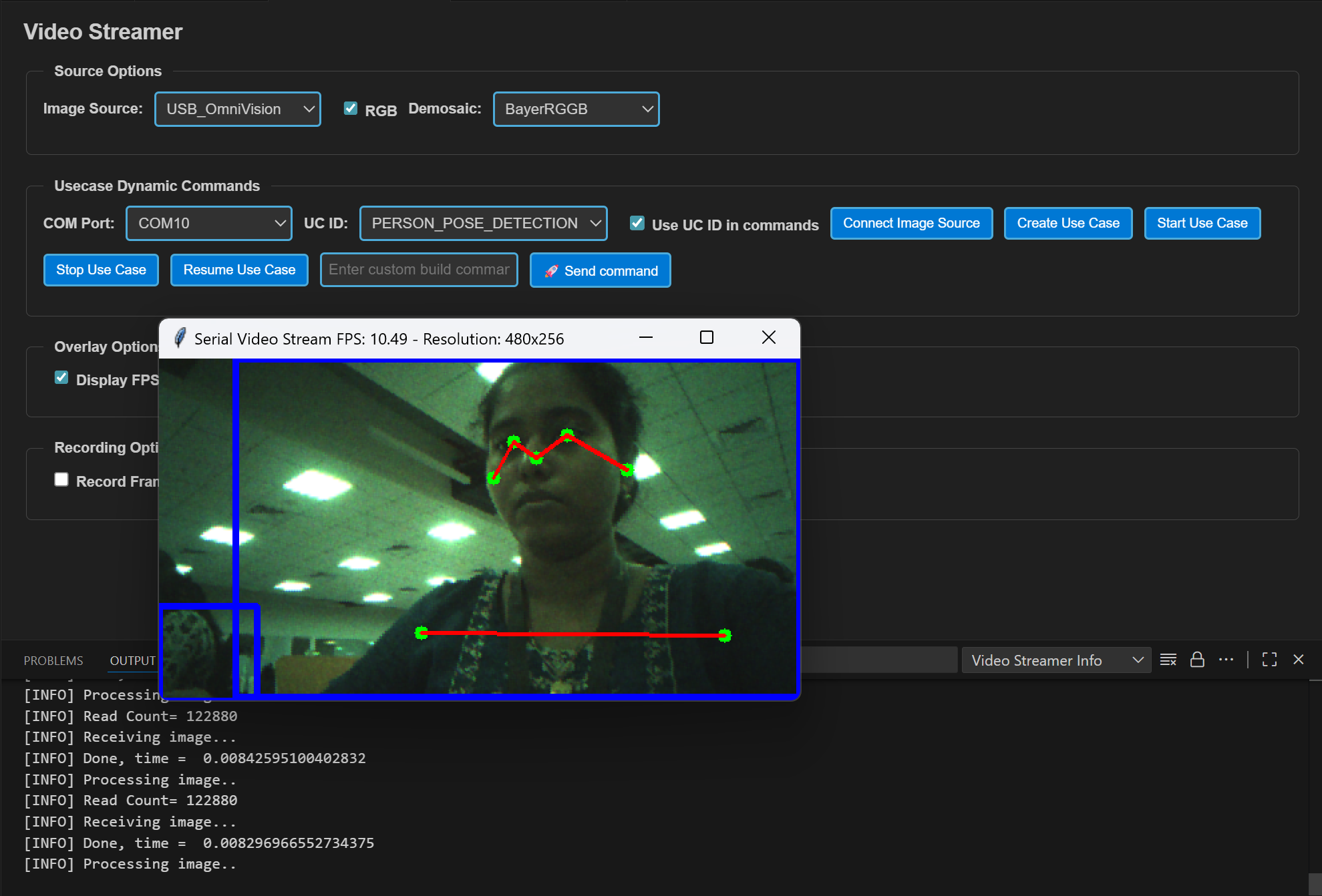
Autorun use cases: If autorun is enabled, after step 4 click Connect Image Source to open the video stream pop-up.