DMA Sample Application
Description
This DMA sample application demonstrates advanced DMA usage including 1D memory transfers, linked descriptor chains, and software-triggered transfers. It highlights DMA channel management, pause/resume control, interrupt-driven completion handling, cache maintenance, and data integrity validation under FreeRTOS.
Prerequisites
Choose one setup path:
Building and Flashing the Example using VS Code
Use the VS Code flow described in the SL2610 guides and VS Code Extension guide:
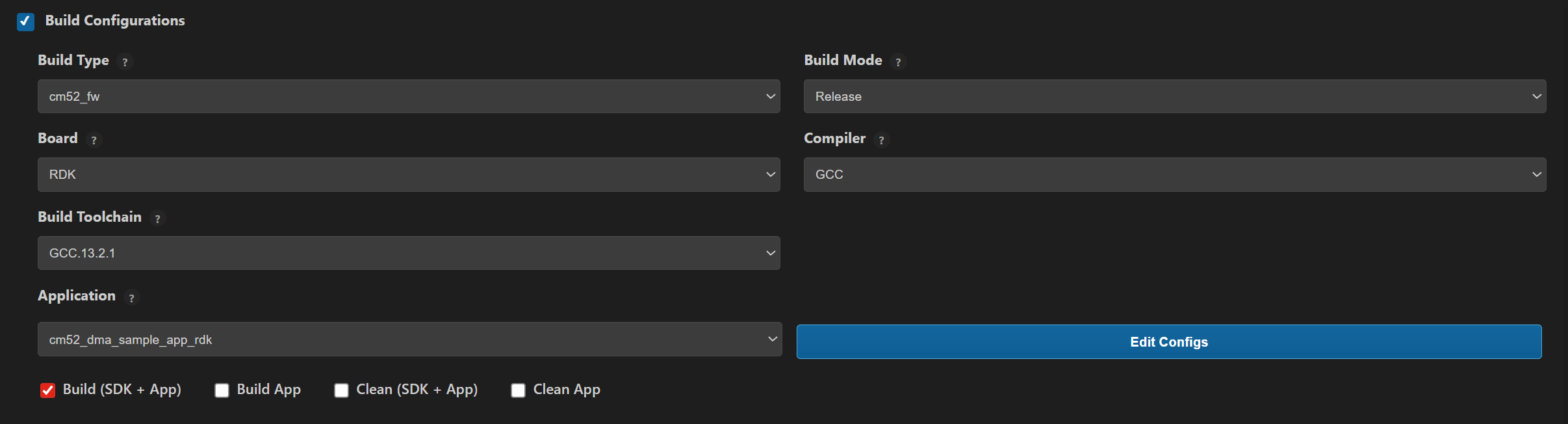
Build (VS Code):
Open Build and Deploy -> Build Configurations.
Select
cm52_dma_sample_app_rdkin the Application dropdown.Build with Build (SDK + App) for the first build, or Build App for rebuilds.
Flash/Image Generation (VS Code):
Note: On Windows, use WSL for SL2610 image generation.
Build the SL2610 bootloader image.
Open SL2610 Image Generation, select the generated application ELF, and click Run.
This is equivalent to
make imagegenand directly generates the system sub-image.
Flash/download the MCU image to target.
Building and Flashing the Example using CLI
Use the CLI flow described in the SL2610 Platform Guide:
Build (CLI):
Build the SL2610 bootloader from SDK root:
make sl2610_bootloader_rdk_defconfig BOARD=SL2610_RDK
make
Build DMA sample app from
<sdk-root>/examples:cd <sdk-root>/examples export SRSDK_DIR=<sdk-root> make cm52_dma_sample_app_rdk_defconfig BOARD=SL2610_RDK BUILD=SRSDK
Image Generation and Flash (CLI):
Note: On Windows, use WSL for SL2610 image generation. In WSL, ensure required tools are installed: Python,
make, and Arm GNU toolchain. You can use the VS Code extension’s Tools Installer in WSL, or follow Linux Environment guide for CLI setup.
Build the SL2610 bootloader image.
Generate the system sub-image:
cd <sdk-root>/examples
export SRSDK_DIR=<sdk-root>
make imagegen
Flash/download image to target.
Running the Application using VS Code Extension
Power the board and press RESET after flashing.
For logging output, connect UART to the target and open a serial console (for example, MobaXterm).
DMA sample logs appear in the serial window.
Expected Logs
0000000000:[0][WRN][LOGR]:Changing logger interface to LOGGER_IF_UART_0
0000000000:[0][INF][SYS ]:M52:: Build Date 24-02-2026 Time 15:46:06 Commit 9d732429
0000000000:[0][INF][SYS ]:sl2610 SDK version 1.3.0
0000000000:[0][INF][DMA ]:Starting DMA Sample Application...
0000000005:[0][INF][DMA ]:Running All DMA Transfer Tests...
0000000010:[0][INF][DMA ]:Channel 0 allocated successfully.
0000000016:[0][INF][DMA ]:[DMA] Preparing 1D transfer: 64 elements from 30001390 to 30001490
0000000024:[0][INF][DMA ]:Transfer Paused.
0000000028:[0][INF][DMA ]:Transfer resumed.
0000000032:[0][INF][DMA ]:[DMA] 1D transfer successful: 64 elements verified
0000000038:[0][INF][DMA ]:Transfer Paused.
0000000042:[0][INF][DMA ]:Transfer resumed.
0000000046:[0][INF][DMA ]:Linked transfers verified successfully.
0000000052:[0][INF][DMA ]:Channel 0 allocated successfully.
0000000057:[0][INF][DMA ]:Final status = 0x10000
0000000062:[0][INF][DMA ]:Transfer completed. Verifying data...
0000000068:[0][INF][DMA ]:SW-triggered DMA transfer successful!
0000000073:[0][INF][DMA ]:All DMA transfers successful.
0000000078:[0][INF][DMA ]:DMA Sample Application Completed.