I2C Expander Sample Application
Description
This I2C expander sample application demonstrates GPIO output control using an external FXL6408 I2C-based GPIO expander. It runs a FreeRTOS task that periodically toggles a selected expander GPIO pin and logs the operation status for validation and debugging.
Prerequisites
Choose one setup path:
Building and Flashing the Example using VS Code
Use the VS Code flow described in the SL2610 guides and VS Code Extension guide:
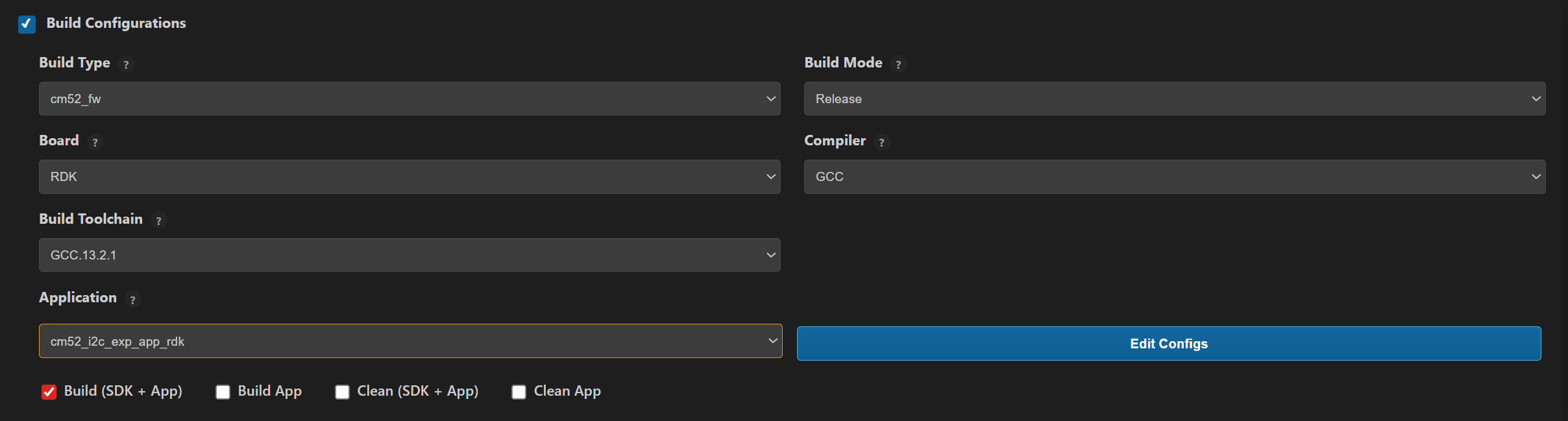
Build (VS Code):
Open Build and Deploy -> Build Configurations.
Select
cm52_i2c_exp_app_rdkin the Application dropdown.Build with Build (SDK + App) for the first build, or Build App for rebuilds.
Flash/Image Generation (VS Code):
Note: On Windows, use WSL for SL2610 image generation.
Build the SL2610 bootloader image.
Open SL2610 Image Generation, select the generated application ELF, and click Run.
This is equivalent to
make imagegenand directly generates the system sub-image.
Flash/download the MCU image to target.
Building and Flashing the Example using CLI
Use the CLI flow described in the SL2610 Platform Guide:
Build (CLI):
Build the SL2610 bootloader from SDK root:
make sl2610_bootloader_rdk_defconfig BOARD=SL2610_RDK
make
Build I2C expander sample app from
<sdk-root>/examples:cd <sdk-root>/examples export SRSDK_DIR=<sdk-root> make cm52_i2c_exp_app_rdk_defconfig BOARD=SL2610_RDK BUILD=SRSDK
Image Generation and Flash (CLI):
Note: On Windows, use WSL for SL2610 image generation. In WSL, ensure required tools are installed: Python,
make, and Arm GNU toolchain. You can use the VS Code extension’s Tools Installer in WSL, or follow Linux Environment guide for CLI setup.
Build the SL2610 bootloader image.
Generate the system sub-image:
cd <sdk-root>/examples
export SRSDK_DIR=<sdk-root>
make imagegen
Flash/download image to target.
Running the Application using VS Code Extension
Power the board and press RESET after flashing.
For logging output, connect UART to the target and open a serial console (for example, MobaXterm).
I2C expander sample logs appear in the serial window.
Expected Logs
Init DDR4 @ 3200
DHL:v0p40 PT:v0p40 ID:0x21010000
USB MOUNTED
0000000000:[0][WRN][LOGR]:Changing logger interface to LOGGER_IF_UART_0
0000000000:[0][INF][SYS ]:M52:: Build Date 22-01-2026 Time 10:59:39 Commit unknown
0000000000:[0][INF][GENR]:I2C Expander GPIO Toggle Task Started
0000000005:[0][INF][GENR]:Controlling FXL6408 pin 5
0000000010:[0][INF][GENR]:FXL6408 pin 5 set to 0
0000001015:[0][INF][GENR]:FXL6408 pin 5 set to 1
0000002019:[0][INF][GENR]:FXL6408 pin 5 set to 0
0000003023:[0][INF][GENR]:FXL6408 pin 5 set to 1
0000004027:[0][INF][GENR]:FXL6408 pin 5 set to 0
0000005031:[0][INF][GENR]:FXL6408 pin 5 set to 1
0000006035:[0][INF][GENR]:FXL6408 pin 5 set to 0
0000007039:[0][INF][GENR]:FXL6408 pin 5 set to 1
0000008043:[0][INF][GENR]:FXL6408 pin 5 set to 0
0000009047:[0][INF][GENR]:FXL6408 pin 5 set to 1
0000010051:[0][INF][GENR]:FXL6408 pin 5 set to 0
0000011055:[0][INF][GENR]:FXL6408 pin 5 set to 1
0000012059:[0][INF][GENR]:FXL6408 pin 5 set to 0
0000013063:[0][INF][GENR]:FXL6408 pin 5 set to 1
0000014067:[0][INF][GENR]:FXL6408 pin 5 set to 0
0000015071:[0][INF][GENR]:FXL6408 pin 5 set to 1
0000016075:[0][INF][GENR]:FXL6408 pin 5 set to 0