SR110 Platform Guide
This document provides SR110-specific hardware setup and platform notes. For more detailed information on the Astra Machina Micro, see the Astra Machina Micro User Guide:
https://cp.synaptics.com/cognidox/download/NR-160034-MS-APPROVED.pdf
For build, image conversion, flashing, and debugging workflows, use:
Platform Overview
SR110 Specifications
Processor: Arm Cortex-M55 CPU
Memory: External flash (e.g., GD25LE128)
Supported Development Kits: SR110_RDK (Astra Machina Micro SR Series - Rev B/C/E)
Hardware Setup
Astra Machina Micro (SR110 RDK)
Connection Steps
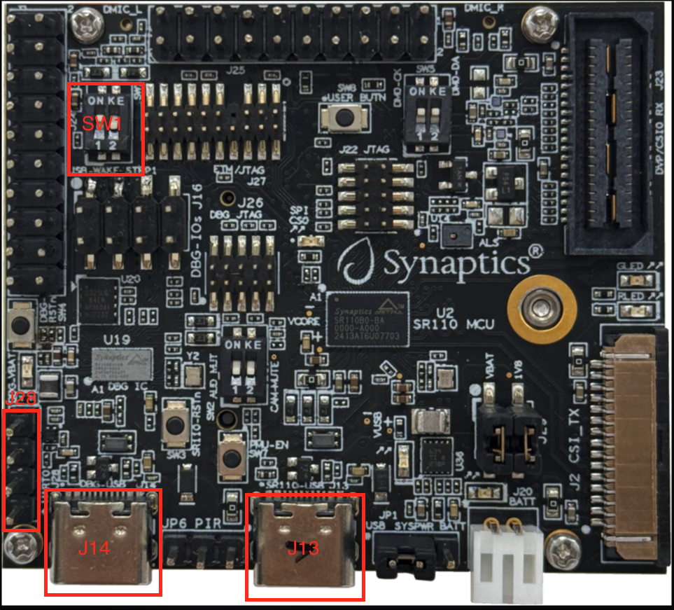
Power and Debug Connection (J14)
Connect Debug IC USB (J14) to your host.
J14 is the Debug IC and the onboard USB‑to‑serial bridge.
It enumerates as:
USB‑HID (CMSIS‑DAP) for SWD debug
USB CDC #1: USB‑to‑UART (UART1 on SR110) for console logs
USB CDC #2: Debug IC firmware update port
Vision USB CDC streaming (J13)
When a vision example is programmed, J13 enumerates as two USB CDC ports:
One for Host API control
One for image streaming
Windows: a driver is required for the streaming port. See the Zadig steps in SR110 Build and Flash with VS Code.
Verify Default Configuration
Confirm jumpers and switches are in default positions (see the Astra Machina Micro User Guide).
SW1.2 boot mode switch:
Position closer to “2”: external flash boot (normal operation)
Position closer to “KE”: external host boot (typically UART via J28)
Identify COM Ports
Windows: Two COM ports appear in Device Manager (Debug IC FW + serial console).
Linux:
/dev/ttyACM0,/dev/ttyACM1macOS:
/dev/tty.usbmodem*
Note: Vision applications also add two CDC ports on J13 for Host API + image streaming.
Verify Hardware Setup
Confirm the board powers up when J14 is connected.
Verify the COM ports appear on the host.
Open a serial terminal (115200 baud, 8N1) and reset the board to see logs.
References
VS Code workflows: Astra MCU SDK VS Code Extension User Guide
CLI workflows: Astra MCU SDK User Guide