Doorbell ML Application
Description
The Doorbell sample application combines the UC_JPEG_PREROLL and IMAGE_STITCHING use cases to detect a person in the camera field of view and capture Full HD (FHD) images when detection occurs.
Captured images can be delivered in two modes:
Delivery Mode |
Description |
Tools for Visualization |
|---|---|---|
USB CDC (to Host PC) |
Sends images via USB CDC to a host PC. |
VS Code Extension |
SPI to Controller |
Sends images over SPI to another Astra Machina Micro acting as controller and receives frames for validation/logging. |
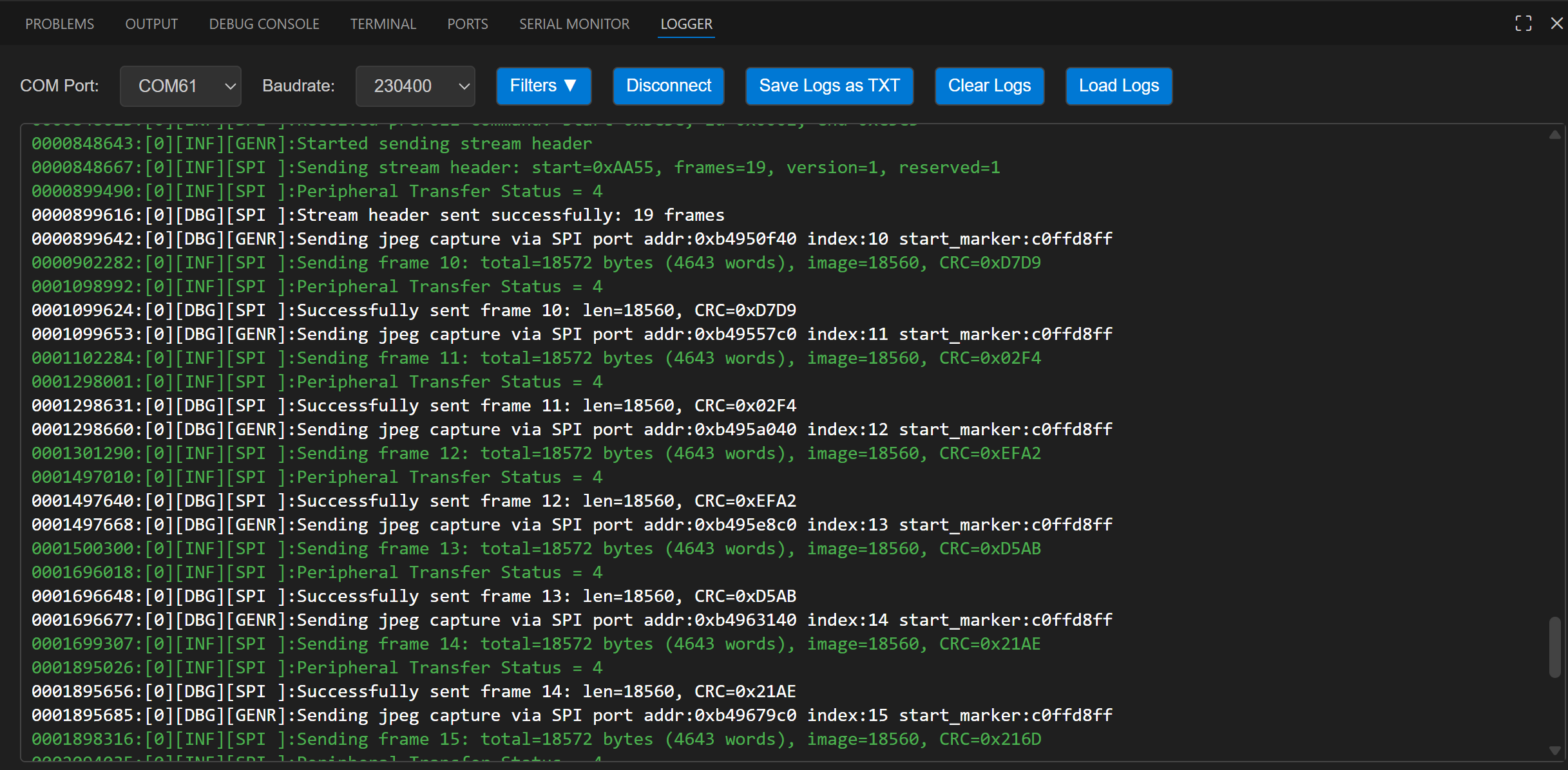
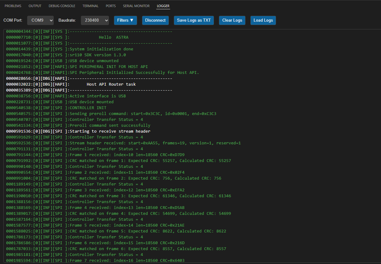
Logger |
Supported Boards
This application supports:
SR110_RDK
Select the defconfig that matches your target board, and the build system will pick the corresponding board-specific hardware setup from hw/<BOARD>/.
Prerequisites
Choose one setup path:
Test Case Selection
Before building, choose the testcase defconfig that matches both your target board and the transfer mode you want to validate.
You can:
Select the required defconfig directly from the application’s
configs/directory.Run
make list_defconfigsfrom the application directory to list all supported defconfigs.
Available defconfigs:
sr110_rdk_cm55_doorbell_gpio_wakeup_defconfigsr110_rdk_cm55_doorbell_timer_wakeup_defconfig
For this app, the default defconfig is:
sr110_rdk_cm55_doorbell_timer_wakeup_defconfig
Building and Flashing the Example using VS Code and CLI
Use the VS Code flow described in the SR110 guide and the VS Code Extension guide:
Build (VS Code):
Open Build and Deploy → Build Configurations.
Select doorbell in the Application dropdown.
Configure wakeup mode in
uc_jpeg_preroll.cusingCONFIG_WAKEUP_TRIGGER:1for timer-based wakeup2for GPIO-based wakeup
Build with Build (SDK + App) for the first build, or Build App for rebuilds.
Build (CLI):
Build from the application directory itself:
cd <sdk-root>/examples/vision_examples/uc_jpeg_preroll
export SRSDK_DIR=<sdk-root>
make <app_defconfig> BUILD=SRSDK
For faster rebuilds when only app code changes, reuse the app-local installed SDK package:
cd <sdk-root>/examples/vision_examples/uc_jpeg_preroll
export SRSDK_DIR=<sdk-root>
make build
If this app has been exported to its own repository, use the same commands from that exported app directory after setting
SRSDK_DIRto the SDK root.
CLI build outputs
The build process will produce the necessary .elf or .axf files for deployment with the installed package.
Flash and Image Generation (VS Code):
Open the Astra MCU SDK VS Code Extension and connect to the Debug IC USB port on the Astra Machina Micro Kit.
Refer to the Astra MCU SDK User Guide for detailed setup steps.
Generate firmware binaries using Build and Deploy → Image Conversion.
Select the required
.axfor.elffile. If the use case is built using the VS Code extension, the file path will be auto-populated.
Flash the application using Build and Deploy → Image Flashing.
Select SWD/JTAG as the interface.
Choose the respective image bins and click Run.
Flash model binary
door_bell_flash(384x512).binat offset0x629000.Model location:
examples/vision_examples/uc_jpeg_preroll/models/
Note: By default, flashing a binary performs sector erase based on binary size. If Full Flash Erase is enabled, tool performs full erase before flashing.
Flash (CLI):
Activate the SDK venv (required for image generation tools):
# Linux/macOS
source <sdk-root>/.venv/bin/activate
# Windows PowerShell
.\.venv\Scripts\Activate.ps1
Generate flash image:
cd <sdk-root>/tools/srsdk_image_generator
python srsdk_image_generator.py \
  -B0 \
  -flash_image \
  -sdk_secured \
  -spk "<sdk-root>/tools/srsdk_image_generator/Inputs/spk_rc4_1_0_secure_otpk.bin" \
  -apbl "<sdk-root>/tools/srsdk_image_generator/Inputs/sr100_b0_bootloader_ver_0x012F_ASIC.axf" \
  -m55_image "<sdk-root>/examples/vision_examples/uc_jpeg_preroll/out/sr110_cm55_fw/release/sr110_cm55_fw.elf" \
  -flash_type "GD25LE128" \
  -flash_freq "67"
Flash the firmware image:
cd <sdk-root>
python tools/openocd/scripts/flash_xspi_tcl.py \
  --cfg_path tools/openocd/configs/sr110_m55.cfg \
  --image tools/srsdk_image_generator/Output/B0_Flash/B0_flash_full_image_GD25LE128_67Mhz_secured.bin \
  --erase-all
Flash model binary at offset
0x629000:cd <sdk-root> python tools/openocd/scripts/flash_xspi_tcl.py \ --cfg_path tools/openocd/configs/sr110_m55.cfg \ --image <path-to-door_bell_flash(384x512).bin> \ --flash-offset 0x629000
Running the Application using VS Code Extension
Windows note: Ensure the USB drivers are installed for streaming. See the Zadig steps in
SR110 Build and Flash with VS Code.
In VS Code, open Video Streamer from the Synaptics sidebar.
For logging output, click SERIAL MONITOR and connect to the DAP logger port on J14.
To make it easier to identify, ensure only J14 is plugged in (not J13).
The logger port is not guaranteed to be consistent across OSes. As a starting point:
Windows: try the lower-numbered J14 COM port first.
Linux/macOS: try the higher-numbered J14 port first.
If you do not see logs after a reset, switch to the other J14 port.
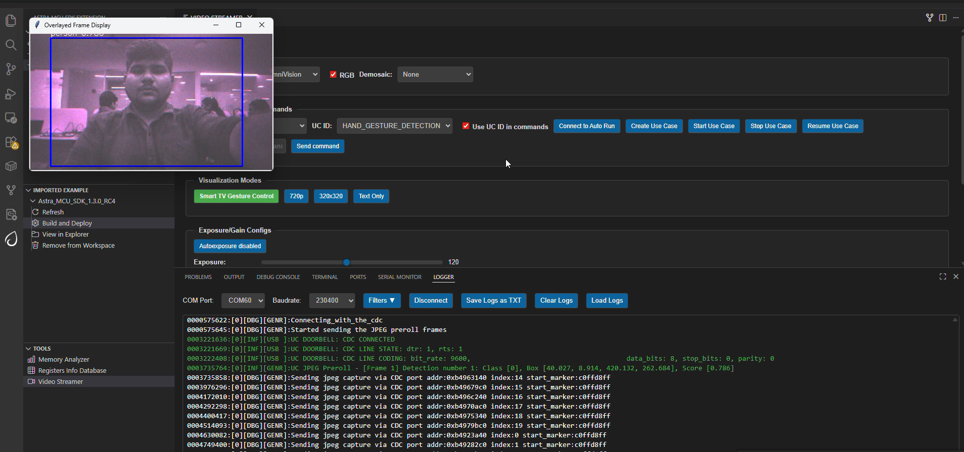
Doorbell application automatically connects to Video Streamer upon reset.
On person detection, video streamer opens with the captured frame and preroll context images.
Wakeup Triggers
Trigger |
Config |
Behavior |
|---|---|---|
Timer |
|
Device wakes every 10 seconds. |
GPIO |
|
Jumper from GND to UART0 RX after 10s of hibernation. |
SPI Pre-roll Use Case
Overview
The SPI Pre-roll feature enables UC_JPEG_PREROLL to capture JPEG pre-roll frames and stream them to a controller (receiver) over SPI.
Peripheral (Sender): Device flashed with Doorbell use case. Captures frames, packages headers/footers, and transmits via SPI.
Controller (Receiver): Device flashed with SPI sample app. Requests pre-roll frames and validates CRC.
Protocol details: SPI Pre-roll Protocol
Configurations
Peripheral (Sender)
Run spi preroll defconfig, for Peripheral device .
make sr110_rdk_cm55_spi_preroll_defconfig BUILD=SRSDK
Controller (Receiver)
Run SPI sample controller defconfig from examples/driver_example/spi_sample_app/ for controller device.
cd examples/driver_example/spi_sample_app/
make sr110_rdk_cm55_spi_sample_app_preroll_controllder_defconfig BUILD=SRSDK
Hardware Setup
Controller Pins
Pin 11 - SPI_MSTR_CLK (GPIO_22)
Pin 12 - SPI_MSTR_CS (GPIO_21)
Pin 13 - SPI_MSTR_MISO (GPIO_24)
Pin 14 - SPI_MSTR_MOSI (GPIO_23)
Peripheral Pins
Pin 7 - SPI_SLV_CLK (GPIO_6)
Pin 8 - SPI_SLV_CS (GPIO_8)
Pin 9 - SPI_SLV_MISO (GPIO_7)
Pin 10 - SPI_SLV_MOSI (GPIO_9)
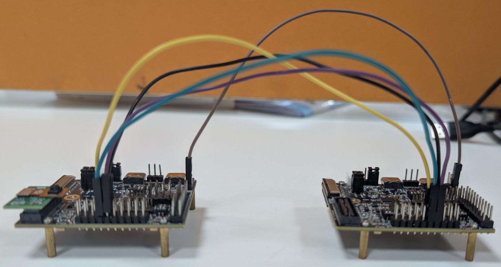
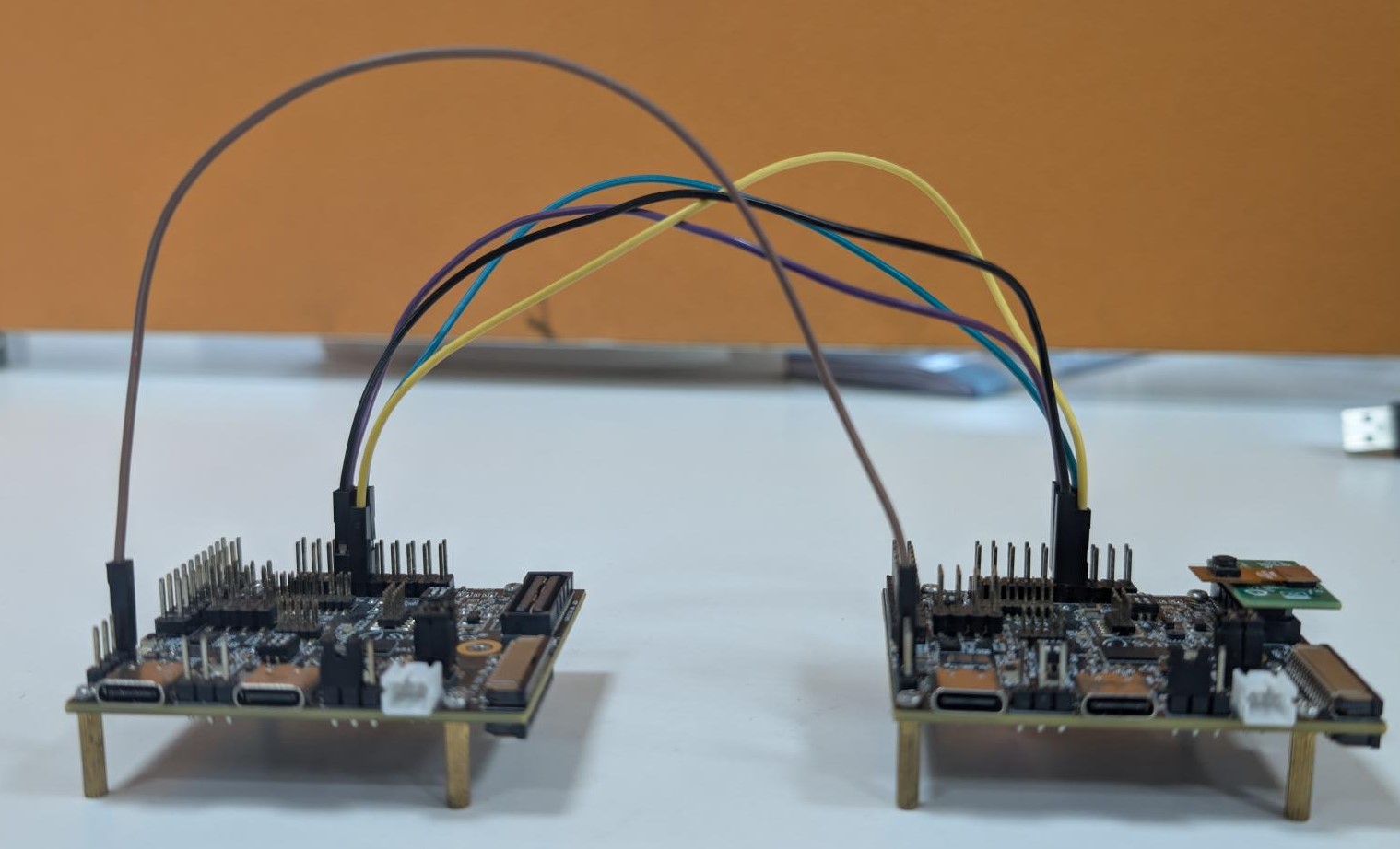
Connections
Pin 11 (SPI_MSTR_CLK) -> Pin 7 (SPI_SLV_CLK)
Pin 12 (SPI_MSTR_CS) -> Pin 8 (SPI_SLV_CS)
Pin 13 (SPI_MSTR_MISO) -> Pin 9 (SPI_SLV_MISO)
Pin 14 (SPI_MSTR_MOSI) -> Pin 10 (SPI_SLV_MOSI)
Connect GND between both boards for stable transfer.
Logger note: Logs are via UART0. Enable UART0 logger in menuconfig. It is recommended to avoid powering DAP SR110 during SPI transfer due to pin conflict in RDK.
Test Procedure
Peripheral (Sender) Steps
Before flashing peripheral image, flash model binary at 0x629000.
After reset, device enters hibernation and captures pre-roll images. On wakeup and detection event, it starts SPI peripheral transfer.
Controller (Receiver) Steps
Flash controller image, then reset controller only after peripheral wakes and starts transfer.
Expected Results
Controller sends pre-roll request header. Peripheral responds with stream header, all pre-roll JPEG frames, and stream end marker over SPI. Controller validates headers, CRC, and footers; logs confirm successful frame reception.
Adapting Pipeline for Custom Object Detection Models
This person detection pipeline can be adapted to work with custom object detection models. However, certain validation steps and potential modifications are required to ensure compatibility.
Prerequisites for Model Compatibility
Before adapting this pipeline for another object detection model, you must verify the following:
1. Model Format Requirements
Your object detection model should be in
.tfliteformatThe model should produce similar output tensor structure (bounding boxes, confidence scores)
2. Vela Compiler Compatibility Check
Step 1: Analyze Original Model
Load your
object_detection_model.tflitefile in NetronDocument the output tensors:
Tensor names
Tensor identifiers/indexes
Quantization parameters (scale and offset values)
Tensor dimensions
Step 2: Compile with Vela
Pass your model through the Vela compiler to generate
model_vela.binormodel_vela.tfliteAnalyze the Vela-compiled model in Netron using the same steps as above
Step 3: Compare Outputs Compare the following between original and Vela-compiled models:
Output tensor indexes/identifiers: Verify if they remain in the same order
Quantization parameters: Check if scale and offset values are preserved
Tensor dimensions: Ensure dimensions match your expected output format
Pipeline Adaptation Process
Case 1: No Changes Required
If the Vela compilation preserves:
✅ Output tensor indexes in the same order
✅ Same quantization scale and offset values
Result: You can proceed with the existing pipeline without modifications.
Case 2: Modifications Required
If the Vela compilation changes:
❌ Output tensor index order
❌ Quantization parameters
Required Actions: Modify the pipeline code as described below.
Code Modifications
If your model’s output tensor indexes change after Vela compilation, you need to update the tensor parameter assignments in uc_jpeg_preroll.c:
Location: detection_post_process function
Original Code:
g_box1_params = &g_all_tens_params[0];
g_box2_params = &g_all_tens_params[1];
g_cls_params  = &g_all_tens_params[2];
Modified Code: Update the array indexes according to your Vela-compiled model’s output tensor identifiers:
// Example: If your model_vela output has different tensor order
g_box1_params = &g_all_tens_params[X];  // Replace X with actual index from Netron
g_box2_params = &g_all_tens_params[Y];  // Replace Y with actual index from Netron
g_cls_params  = &g_all_tens_params[Z];  // Replace Z with actual index from Netron